
A kind of material guide device for stamping side material roll tape coiling of stamping parts

A material guide device and a technology for stamping parts, which are applied in the field of material guide devices for stamping edge material tape coiling of stamping parts, can solve the problems that the stamping machine cannot work continuously, increase the cost of equipment, and shift the edge of the material strip, and achieve convenient The effect of moving the raw material belt, reducing equipment cost and improving work efficiency

Active Publication Date: 2022-03-29
陈茂林
View PDF0 Cites 0 Cited by
  • Summary
  • Abstract
  • Description
  • Claims
  • Application Information

AI Technical Summary

Problems solved by technology

[0002] After the notebook fan blades are stamped and formed, the waste tape needs to be collected by coiling. The existing reel is used for direct coiling or waste coiling and collection by a mobile reel. The former is easy to form a U-shaped waste drum during the coiling process. , leading to the need for coiling during the stamping process, the latter is likely to cause the edge of the strip to shift during the stamping process during the coiling process, resulting in poor stamping accuracy, and can only form a width of 20-30cm width waste roll, resulting in handling costs High, a stamping machine is required to be equipped with a coiling device, and the equipment cost is high. In order to reduce the cost, there is also a cutting process for the waste. After the stamping, the waste is sheared, and the cut waste block is bagged. For transportation, it is necessary to add a shearing machine at the back end of the punching machine, which increases the cost of the equipment, and workers are required to replace the waste belt at any time. When the waste bag is 40-50 kg slower, it is necessary to stop the machine to replace the waste bag, which causes the punching machine to not work continuously. Moreover, safety hazards such as hand scratches and crush injuries are prone to occur during the bag change process.

Method used


Image

  • A kind of material guide device for stamping side material roll tape coiling of stamping parts
  • A kind of material guide device for stamping side material roll tape coiling of stamping parts
  • A kind of material guide device for stamping side material roll tape coiling of stamping parts

Examples


Embodiment approach

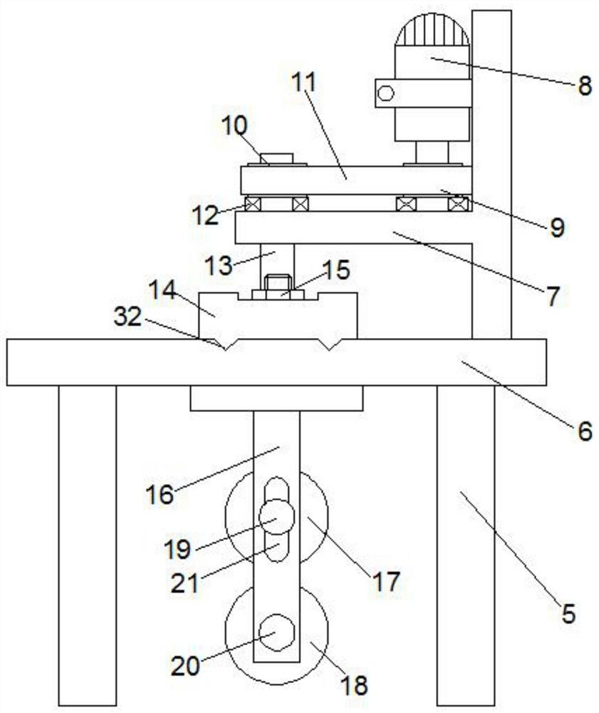
[0029] In a preferred embodiment, the drive device includes a motor 8 and a cam 26 connected to the motor 8, a slide seat 27 is provided at the end of the guide slide 14, and a housing hole 34 for accommodating the cam 26 is provided in the slide seat 27 In this embodiment, the sliding seat 27 is provided with a chute I31, and the end of the guide slide 14 is provided with a pin shaft 30 sliding along the chute I31, and the motor drives the cam 26 to rotate, so that the sliding seat 27 deflects and moves along the cam 26 , under the action of the chute I31 and the pin shaft 30, the material guide slide 14 is moved back and forth along the slide rail, this structure is conducive to waste coiling, and avoids the side material band from forming piles on the waste roll.

[0030]In a preferred embodiment, the accommodating hole 34 is horizontally arranged in the sliding seat 27, and the accommodating hole 34 is provided with a first circular arc inner wall in contact with the distal...


PUM


Abstract

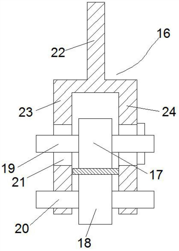
The invention discloses a material guide device for coiling strips of stamping edge material of stamping parts, which comprises a frame arranged between a punching machine and a coiling machine, a slide rail is arranged on the frame, and a slide rail is mounted on the slide rail. A material guide slide is provided, the guide slide is connected with a driving device, the bottom of the guide slide is provided with a material guide frame, and the material guide frame includes an upper material guide shaft, an upper material guide set on the upper material guide shaft Roller, lower material guide shaft and the lower material guide roller sleeved on the lower material guide shaft, a gap is provided between the upper material guide roller and the lower material guide roller to accommodate the passage of the edge material belt; There are guide slides and guide carriages, and the upper and lower guide rollers on the guide carriage are used to clamp and flatten the side material belt, which is convenient for winding up the side material belt. The material carriage slides on the machine frame, which is convenient for the edge material to be coiled back and forth on the reel of the coiler, which is convenient for transportation and reduces equipment cost.

Description

technical field [0001] The invention relates to the technical field of coiling and production of scrap strips, in particular to a material guide device for coiling strips of stamping edge material of stamping parts. Background technique [0002] After the notebook fan blades are stamped and formed, the waste tape needs to be collected by coiling. The existing reel is used for direct coiling or waste coiling and collection by a mobile reel. The former is easy to form a U-shaped waste drum during the coiling process. , leading to the need for coiling during the stamping process, the latter is likely to cause the edge of the strip to shift during the stamping process during the coiling process, resulting in poor stamping accuracy, and can only form a width of 20-30cm width waste roll, resulting in handling costs High, a stamping machine is required to be equipped with a coiling device, and the equipment cost is high. In order to reduce the cost, there is also a cutting process ...

Claims


Application Information

Patent Timeline
Patent Type & Authority Patents(China)
IPC IPC(8): B21C47/34B21C47/12B21C47/26
CPCB21C47/34B21C47/12B21C47/26
Inventor 陈茂林陈洪均谢洪权邹慧新
Owner 陈茂林
Learn More