Servo motor and automatic production equipment and method thereof

A technology for production equipment and servo motors, applied in the field of servo motors, can solve problems such as poor assembly quality of servo motors

Inactive Publication Date: 2020-09-04
高鑫斌
View PDF0 Cites 5 Cited by
  • Summary
  • Abstract
  • Description
  • Claims
  • Application Information

AI Technical Summary

Problems solved by technology

[0004] The purpose of the present invention is to solve the above-mentioned problem of poor assembly quality of existing servo motors, and provide an automatic production equipment for servo motors, which improves the assembly accuracy of the housing and bearings through the housing bearing assembly device; The assembly device improves the feeding efficiency of magnetic tiles; through the cooperation of the magnetic tile feeding assembly device and the slingshot feeding device, it is convenient to insert the slingshot between the magnetic tiles, and at the same time, it is convenient to put the magnetic tile and the slingshot into the shell together, improving the assembly efficiency ; The magnetization efficiency and magnetization quality are further improved through the magnetization device

Method used


Image

  • Servo motor and automatic production equipment and method thereof
  • Servo motor and automatic production equipment and method thereof
  • Servo motor and automatic production equipment and method thereof

Examples


Embodiment Construction

[0038] The specific implementation manner of the present invention will be described in detail below in conjunction with the accompanying drawings.

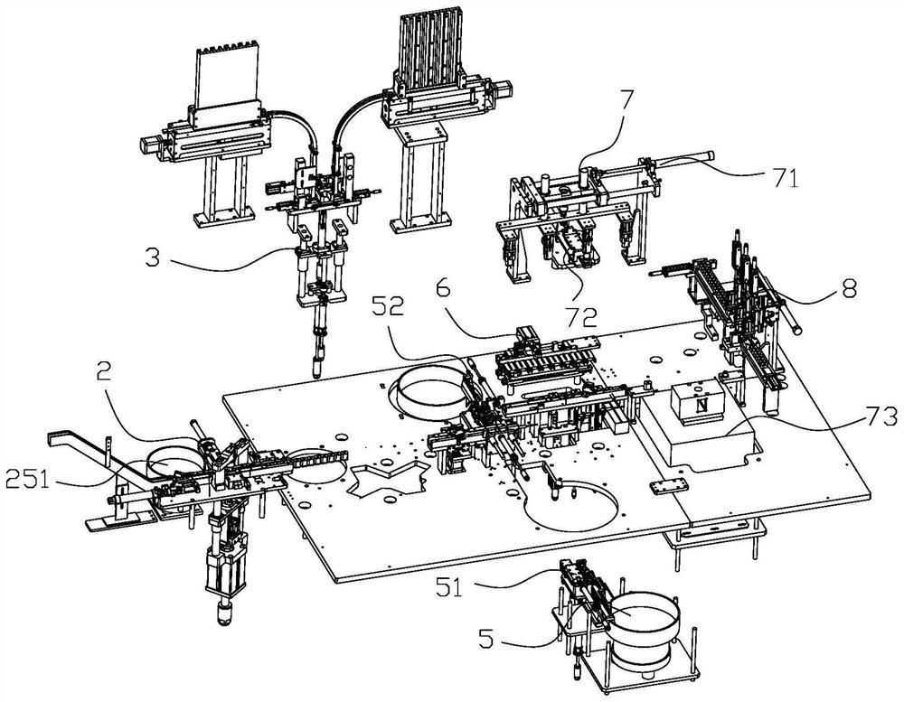
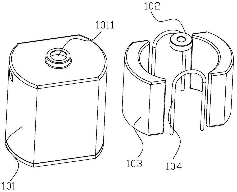
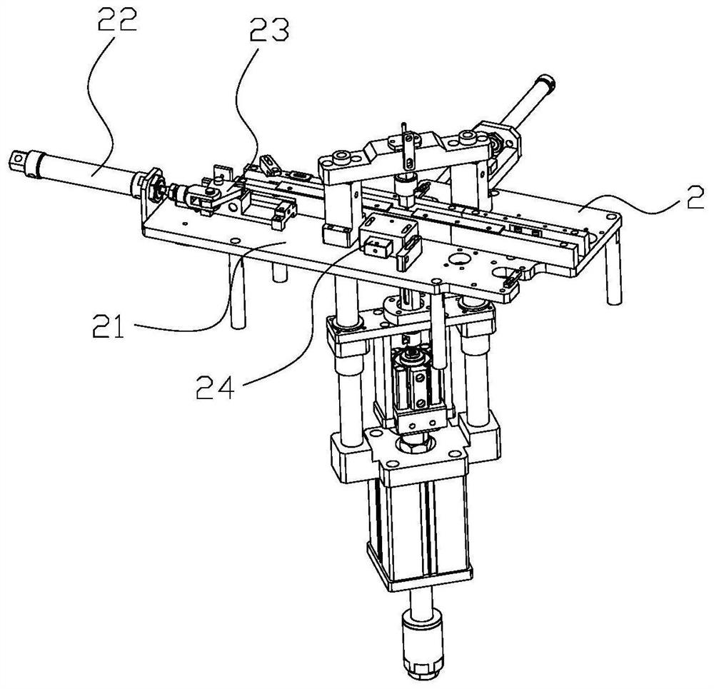
[0039] Such as figure 1 As shown, a servo motor automatic production equipment, the equipment includes a frame and a shell bearing assembly device 2 on it, a magnetic tile feeding assembly device 3, a slingshot feeding device 5, a transfer device 6, and a magnetizing device 7 And discharge conveying device 8; shell bearing feeding assembly device 2, magnetic tile feeding assembly device 3, slingshot feeding device 5, transfer device 6, magnetizing device 7 and discharging conveying device 8 to feed to the discharging direction Arranged in sequence; shell bearing loading assembly device 2 is used to load the shell and bearing and install the bearing on the shell; magnetic tile feeding assembly device 3 is used to load two symmetrical magnetic tiles and place the two magnetic tiles Loaded into the shell, the slingshot feeding devi...


PUM


Abstract

The invention relates to the technical field of servo motors and in particular to automatic production equipment for a servo motor. The automatic production equipment comprises a rack, a shell and bearing feeding and assembling device, a magnetic shoe feeding and assembling device, a slingshot feeding device, a transferring device, a magnetizing device and a discharging and conveying device. The shell and bearing feeding and assembling device, the magnetic shoe feeding and assembling device, the slingshot feeding device, the transferring device, the magnetizing device and the discharging and conveying device are arranged on the rack. The shell and bearing feeding and assembling device is used for feeding a shell and a bearing and installing the bearing on the shell. The magnetic shoe feeding and assembling device is used for feeding two symmetrical magnetic shoes and installing the two magnetic shoes into the shell, and the slingshot feeding device is used for conveying two slingshotsand installing the two slingshots between the two magnetic shoes. The transferring device is used for transferring assembled units to the magnetizing device one by one. The magnetizing device is usedfor magnetizing the assembled units. The automatic production equipment for the servo motor has the advantages that the bearing assembling quality is improved, the matching degree of the magnetic shoes and the slingshots is improved, the magnetic shoe assembling quality and efficiency and the slingshot assembling quality and efficiency are improved, the magnetizing efficiency and quality are improved, and the assembling efficiency of the whole servo motor is improved.

Description

technical field [0001] The invention relates to the technical field of servo motors, in particular to an automatic production equipment and production method of servo motors. Background technique [0002] Servo motor refers to the engine that controls the operation of mechanical components in the servo system, and is an auxiliary motor indirect speed change device. The servo motor includes a housing and a bearing inside, two magnetic tiles and two slingshots, and the two slingshots are located between the two magnetic tiles. During the production process of the servo motor, the casing is fed with material first, and then the bearing is fed and installed into the shaft hole on the top of the casing, and then the two magnetic tiles are respectively conveyed to the left and right sides of the bottom of the casing, and the two The slingshot is transported to the front and rear sides of the two magnetic tiles, the two slingshots are squeezed by the two magnetic tiles, and finall...

Claims


Application Information

Patent Timeline
Patent Type & Authority Applications(China)
IPC IPC(8): B23P21/00H02K15/00
CPCB23P21/004H02K15/00
Inventor 高鑫斌乔随有宋书田
Owner 高鑫斌
Why Eureka
Try Eureka