River remote sensing monitoring device based on unmanned aerial vehicle

A remote sensing monitoring and unmanned aerial vehicle technology, applied in the direction of measuring devices, aircraft power units, unmanned aerial vehicles, etc., can solve the problems of high performance requirements of unmanned aerial vehicles, inability to detect water flow speed, and inaccurate results, etc., to achieve Reduce the difficulty of manipulation, increase the shooting angle, and reduce the cost

Inactive Publication Date: 2020-09-04
嘉兴勤慎智能技术有限公司
View PDF6 Cites 2 Cited by
  • Summary
  • Abstract
  • Description
  • Claims
  • Application Information

AI Technical Summary

Problems solved by technology

First, the camera on the drone is fixed, and the angle is fixed when taking remote sensing shots of the river. It is necessary to control the rotation of the drone to shoot multi-angle videos. The control of the drone and the performance of the drone itself are too demanding. Second, this type of detection is only carried out on the visual screen, and the actual detection of the water flow speed in the river cannot be carried out, and the results simulated by the follow-up simulation software are not accurate.

Method used


Image

  • River remote sensing monitoring device based on unmanned aerial vehicle
  • River remote sensing monitoring device based on unmanned aerial vehicle
  • River remote sensing monitoring device based on unmanned aerial vehicle

Examples


Embodiment 1

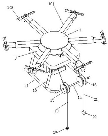
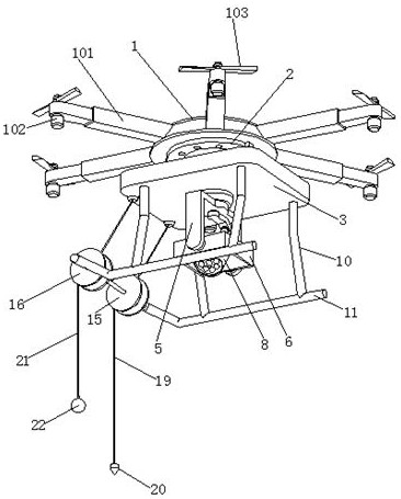
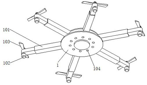
[0034] Embodiment 1 introduces a kind of river regime remote sensing monitoring device based on unmanned aerial vehicles, with reference to the attached figure 1 , attached figure 2 And attached image 3 , its main structure includes a UAV body 1, and several rotor brackets 101 are arranged on the circumference of the UAV body 1. Specifically, the number of rotor brackets 101 provided on the circumference of the UAV body 1 in this embodiment is six , and each rotor bracket 101 is set around the UAV body 1 at an equal fan-shaped angle. The lower surfaces of the outer ends of the six rotor brackets 101 are provided with first micromotors 102 , and the output shafts of the first micromotors 102 pass through the tops of the outer ends of the rotor brackets 101 to be provided with propeller blades 103 .

[0035] The lower surface of the UAV body 1 is connected with a connecting ring 2, and the lower end of the connecting ring 2 is connected with a rectangular carrier 3. For deta...

Embodiment 2

[0039] Embodiment 2 has introduced a kind of river regime remote sensing monitoring device based on the improvement on embodiment 1, refer to the attached figure 1 , attached figure 2 And attached image 3 , its main structure includes a UAV body 1, and several rotor brackets 101 are arranged on the circumference of the UAV body 1. Specifically, the number of rotor brackets 101 provided on the circumference of the UAV body 1 in this embodiment is six , and each rotor bracket 101 is set around the UAV body 1 at an equal fan-shaped angle. The lower surfaces of the outer ends of the six rotor brackets 101 are provided with first micromotors 102 , and the output shafts of the first micromotors 102 pass through the tops of the outer ends of the rotor brackets 101 to be provided with propeller blades 103 .

[0040] The lower surface of the UAV body 1 is connected with a connecting ring 2, and the lower end of the connecting ring 2 is connected with a rectangular carrier 3. For de...

Embodiment 3

[0044] Embodiment 3 has introduced a kind of river regime remote sensing monitoring device based on the improvement on embodiment 2, refer to the attached figure 1 , attached figure 2 And attached image 3 , its main structure includes a UAV body 1, and several rotor brackets 101 are arranged on the circumference of the UAV body 1. Specifically, the number of rotor brackets 101 provided on the circumference of the UAV body 1 in this embodiment is six , and each rotor bracket 101 is set around the UAV body 1 at an equal fan-shaped angle. The lower surfaces of the outer ends of the six rotor brackets 101 are provided with first micromotors 102 , and the output shafts of the first micromotors 102 pass through the tops of the outer ends of the rotor brackets 101 to be provided with propeller blades 103 .

[0045] The lower surface of the UAV body 1 is connected with a connecting ring 2, and the lower end of the connecting ring 2 is connected with a rectangular carrier 3. For de...


PUM


Abstract

The invention relates to the technical field of unmanned aerial vehicle monitoring, and particularly discloses a river remote sensing monitoring device based on an unmanned aerial vehicle. The devicecomprises an unmanned aerial vehicle body, a plurality of rotor wing supports are arranged on the circumferential surface of the unmanned aerial vehicle body, first micro motors are arranged on the lower surfaces of the outer ends of the rotor wing supports, and output shafts of the first micro motors penetrate through the top ends of the outer ends of the rotor wing supports to be provided with propeller blades. According to the invention, the unmanned aerial vehicle flies above a river, when the river potential of the river is specifically detected, a third motor is controlled to rotate through a remote sensing technology, the gravity block at the lower end of the first guide rope sinks into river water, a floating ball is floated at the lower end of the second guide rope on the upper surface of river water, the first guide rope and the second guide rope are arranged in the river water flowing direction and flow in the river water flowing direction until the second guide rope is pulled, the included angle between the first guide rope and the second guide rope is shot through the camera, meanwhile, the tension on the first guide rope and the tension on the second guide rope are read out, the flow velocity of the river is calculated, and the calculated result is more accurate compared with the result obtained through simulation software.

Description

technical field [0001] The invention relates to the technical field of unmanned aerial vehicle monitoring, and specifically discloses an unmanned aerial vehicle-based remote sensing monitoring device for river regime. Background technique [0002] Regular measurement of the plane state of river flow is one of the important contents of river channel observation. The river regime characteristics of various natural channels are different. Generally, the river regime of meandering channels is relatively stable, while that of wandering channels is unstable. The purpose of river regime observation is to analyze the change law by observing and accumulating data, and then forecast the river regime change, so as to take timely measures to ensure flood control safety and engineering benefits. At present, the traditional monitoring of river regime is that the operator drives the ship into the river, and then conducts manual monitoring, which is not only time-consuming, laborious, cost...

Claims


Application Information

Patent Timeline
Patent Type & Authority Applications(China)
IPC IPC(8): B64D47/08B64D47/00B64C27/08B64C27/14B64C27/32B64D27/24B64D31/00G01C13/00
CPCB64D47/08B64D47/00B64C27/08B64C27/14B64C27/32B64D27/24B64D31/00G01C13/002B64U50/19B64U2101/30B64U10/10B64U2101/00Y02A90/30
Inventor 牛庾鑫
Owner 嘉兴勤慎智能技术有限公司
Why Eureka
Try Eureka