
Inverted type cantilever scaffold erecting method

A technology for cantilevering scaffolding and scaffolding, which is applied to the attachment of scaffolding, the connection of scaffolding, and the scaffolding supported by house structure, etc., to achieve the effect of ensuring safety performance, speeding up construction progress, and reducing welding open flame operations.

Inactive Publication Date: 2020-09-04
湖南省第四工程有限公司
View PDF7 Cites 2 Cited by
  • Summary
  • Abstract
  • Description
  • Claims
  • Application Information

AI Technical Summary

Problems solved by technology

[0003] The technical problem to be solved by the present invention is: to overcome the defects of the conventional cantilevered scaffold erection method, and provide a reverse-operated cantilevered scaffold erection method to eliminate the major safety hazards caused by the lack of protection when installing the cantilevered steel beam, and reduce the risk of erection. The process of dismantling temporary protection to speed up the construction progress

Method used


Image

  • Inverted type cantilever scaffold erecting method
  • Inverted type cantilever scaffold erecting method
  • Inverted type cantilever scaffold erecting method

Examples


example 1

[0040] The fourth bid section of the construction and installation project of a resettlement community, the construction area of ​​the project is 56963.47 m2, and the cost is 114.1933 million yuan. There is one basement floor and 24 floors underground. The 1-3 floor podium adopts ordinary floor-to-ceiling scaffolding, and the 4th floor begins to use 16# I-beam cantilevered scaffolding. This project adopts the construction technology of inverted cantilevered scaffolding, and the construction quality and safety are reliably guaranteed, without any size safety. The accident occurred, and the construction period was shortened by about 6 days compared with the conventional construction technology, and the cost of materials and labor was reduced by 27,000 yuan, and the economic benefits were obvious.

example 2

[0042]The first phase of a school renovation and expansion project, with a total construction area of ​​about 100075.91m2. Among them, the comprehensive building (15#) and the shift building (23#) are high-rise buildings. During the main construction, the cantilevered scaffolding will be erected in three sections from the second floor above. . The cantilevered scaffolding adopts the construction technology of inverted cantilevered scaffolding, which avoids the lack of protection of the outer frame when the cantilevered scaffolding is erected, eliminates potential safety hazards, and has no safety accidents during the construction process, which has won unanimous praise from the construction and supervision units. Compared with the conventional construction technology, the construction period is shortened by about 7 days, and the cost of materials and labor is reduced by 32,000 yuan, and the economic benefits are obvious.


PUM


Abstract

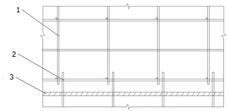
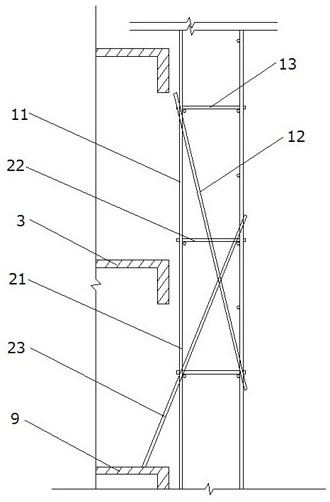
The invention provides an inverted type cantilever scaffold erecting method. The method comprises the following steps of 1) erecting a first-step frame of an upper-layer scaffold, wherein the first-step frame of the upper-layer scaffold is pre-erected on a lower-layer scaffold, so that the bottom end of a cantilever vertical rod in the first-step frame is higher than a cantilevered floor; 2) pre-embedding anchoring parts in the cantilevered floor, wherein the anchoring parts are pre-embedded according to the mounting position of a cantilever steel beam; 3) installing the cantilever steel beam,wherein the cantilever steel beam is installed through the anchoring parts, and a positioning support is installed on the cantilever steel beam; 4) releasing the first-step frame to the cantilever steel beam, wherein after the cantilever steel beam is installed, the cantilever vertical rod is lowered onto the cantilever steel beam and positioned with the positioning support; 5) erecting an upper-layer frame body of the upper-layer scaffold, wherein after the first-step frame is loosened, the upper-layer frame body of the upper-layer scaffold is erected according to a conventional lapping method. According to the erecting method, the great potential safety hazard of mounting protection missing of the cantilever steel beam is eliminated, the safety protection of the cantilever layer frame body is achieved by 100% in place, and the safety performance of the cantilever layer frame body is effectively guaranteed.

Description

technical field [0001] The invention belongs to the field of building engineering construction, and in particular relates to a method for erecting a reverse-operated cantilevered scaffold. Background technique [0002] Cantilevered scaffolding is widely used in the outer frame of the main structure of multi-storey or high-rise buildings. The conventional method of erecting cantilevered scaffolding is to pre-embed the anchor ring in the cantilever layer, and then hang it after the concrete pouring is completed and reaches a certain strength. The installation of the steel beams, and finally the erection of the cantilevered frame. When erecting the cantilevered frame body, since the workers have no external protection, there are great potential safety hazards, and it is often necessary to erect additional temporary protection to ensure the safety of the construction workers, resulting in many construction procedures and a long construction period. In addition, the vertical rod...

Claims


Application Information

Patent Timeline
IPC IPC(8): E04G3/18E04G3/22E04G5/00E04G5/04E04G5/16E04G7/22
CPCE04G3/18E04G3/22E04G5/007E04G5/04E04G5/16E04G7/22
Inventor 刘令良胡小兵孔正武蒋涛张磊
Owner 湖南省第四工程有限公司
Features
  • Generate Ideas
  • Intellectual Property
  • Life Sciences
  • Materials
  • Tech Scout
  • Unparalleled Data Quality
  • Higher Quality Content
  • 60% Fewer Hallucinations
Learn More