Tunnel smoke exhaust system and tunnel

A smoke exhaust system and smoke exhaust channel technology, which is applied in mine/tunnel ventilation, pump control, mining equipment, etc., can solve the problems of large air leakage, large attenuation, and delayed smoke exhaust response, and achieve the effect of improving the effect.

Pending Publication Date: 2020-09-04
CHINA RAILWAY FIFTH SURVEY & DESIGN INST GRP
View PDF0 Cites 2 Cited by
  • Summary
  • Abstract
  • Description
  • Claims
  • Application Information

AI Technical Summary

Problems solved by technology

[0004] (1) The number of smoke exhaust outlets is large, resulting in a large amount of air leakage, especially when the smoke is exhausted at the far end, the attenuation is large, resulting in poor smoke exhaust effect;
[0005] (2) The smoke exhaust air volume of each smoke exhaust port is uneven, and the air volume of each smoke exhaust port is difficult to balance;
[0006] (3) It is necessary to install a smoke exhaust fan with a large pressure head and a high power at both ends of the smoke exhaust channel, which requir

Method used


Image

  • Tunnel smoke exhaust system and tunnel
  • Tunnel smoke exhaust system and tunnel
  • Tunnel smoke exhaust system and tunnel

Examples


Embodiment 1

[0035] This embodiment provides a tunnel smoke exhaust system, which can be applied to tunnels in mountainous areas, underground, and under the sea. Well Tunnel. A long tunnel is a tunnel with a length of more than 5 kilometers. The above-mentioned tunnel can be a road tunnel, a railway tunnel or an urban rail vehicle tunnel. This embodiment only takes a road tunnel as an example to describe the smoke exhaust system in detail. Those skilled in the art can directly apply the technical solution provided by this embodiment to other type of tunnel, or apply the technical solution provided in this embodiment to other types of tunnels after adaptive modification.

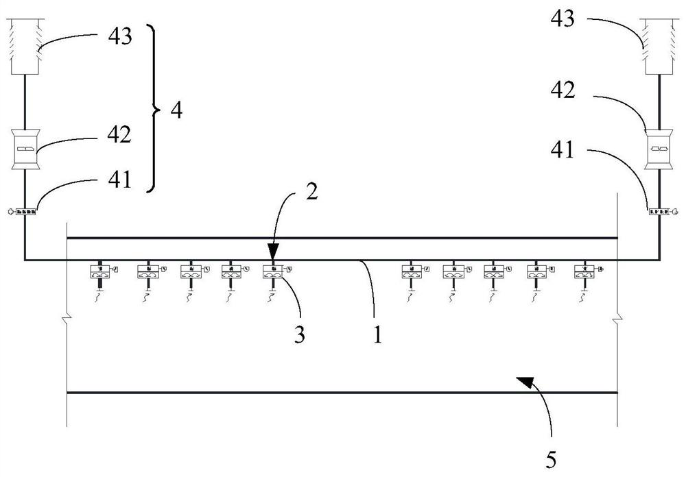
[0036] figure 1 It is an overall schematic diagram of the application of the tunnel smoke exhaust system provided in Embodiment 1 of the present application to a tunnel. Such as figure 1 As shown, this embodiment provides a tunnel smoke exhaust system, including: a smoke exhaust channel 1 , a smoke exhaust port 2 , an...

Embodiment 2

[0049] This embodiment provides a specific implementation of the tunnel smoke exhaust system on the basis of the above embodiments.

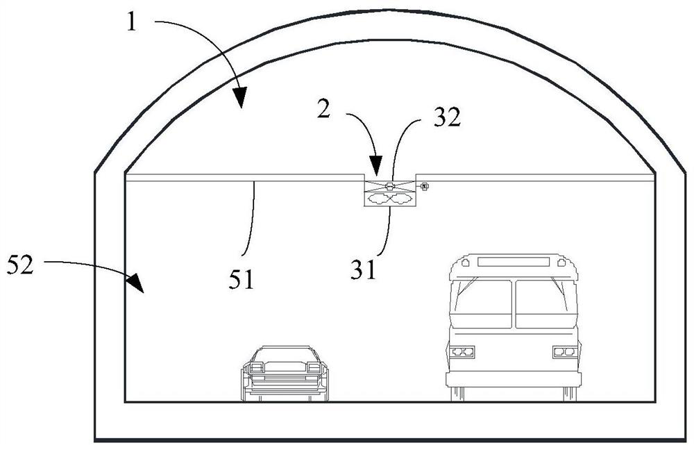
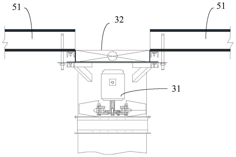
[0050] figure 2 The tunnel section view provided for Embodiment 2 of the present application, image 3 A schematic structural diagram of an internal smoke exhaust fan and an internal smoke exhaust valve provided at the smoke exhaust port of the tunnel smoke exhaust system provided in Example 2 of the present application. Such as figure 2 As shown, a partition wall 51 is provided above the tunnel 5 provided in this embodiment, and the partition wall 51 extends along the horizontal direction and is formed between the two side walls of the tunnel. The space below the partition wall 51 is the driving passage 52 , and the space above the partition wall 51 is the smoke exhaust passage 1 .

[0051] A plurality of smoke outlets 2 are opened on the partition wall 51, and the plurality of smoke outlets 2 are arranged at intervals along the length dir...

Embodiment 3

[0061] This embodiment is based on the above-mentioned technical solution, and provides another implementation manner in which the smoke exhaust system is applied in a tunnel.

[0062] Figure 4 The tunnel section view provided for the third embodiment of the present application, Figure 5 A structural schematic diagram of an internal smoke exhaust fan and an internal smoke exhaust valve provided at the smoke exhaust port of the tunnel smoke exhaust system provided in Example 3 of the present application. Such as Figure 4 As shown, the partition wall 51 extends in the vertical direction and is located between the top wall and the bottom wall of the tunnel 5 . There are two partition walls 51 arranged side by side in the middle of the tunnel 5 . A smoke exhaust channel 1 is formed between the two partition walls 51 , the left side of the left partition wall 51 is the driving passage 52 , and the right side of the right partition wall 51 is the driving passage 52 . The driv...


PUM


Abstract

The embodiment of the invention provides a tunnel smoke exhaust system and a tunnel. The smoke exhaust system comprises a smoke exhaust channel, a smoke outlet, an internal smoke exhaust device and end smoke exhaust devices; the smoke exhaust channel is disposed in the tunnel and extends in the length direction of the tunnel; the smoke exhaust channel is separated from a driving channel of the tunnel through a dividing wall; the smoke outlet is formed in the partition wall; the internal smoke exhaust device is arranged at the smoke outlet; when the smoke exhaust system is in a non-smoke-exhaust working condition, the internal smoke exhaust device is in a stop state so as to seal the smoke outlet; when the smoke exhaust system is in a smoke exhaust working condition, the internal smoke exhaust device is in a working state to open the smoke outlet to exhaust smoke to the smoke exhaust tunnel; the end smoke exhaust devices are arranged at the two ends of the smoke exhaust channel; when the smoke exhaust system is in the non-smoke-exhaust working condition, the end smoke exhaust devices are in a closed state; and when the smoke exhaust system is in the smoke exhaust working condition,the end smoke exhaust devices are in a working state to exhaust smoke from the smoke exhaust channel. According to the tunnel smoke exhaust system and the tunnel provided by the embodiment, the smokeexhaust speed and the smoke exhaust effect can be improved.

Description

technical field [0001] The present application relates to tunnel smoke exhaust technology, in particular to a tunnel smoke exhaust system and a tunnel. Background technique [0002] A tunnel is a building opened underground, in a mountainous area, or underwater, for the passage of cars, trains, or urban rail vehicles. The tunnel is usually equipped with a smoke exhaust system, which is suitable for exhausting the internal smoke as soon as possible when a fire occurs in the tunnel. The smoke exhaust system includes: a smoke exhaust channel extending along the length of the tunnel and a number of smoke exhaust outlets. The smoke exhaust outlets are connected to the smoke exhaust channels. exhaust from the wind shaft. For terrain environments that are easy to construct, artificial islands or intermediate air shafts can be installed in the middle of the tunnel for horizontal smoke exhaust. However, for terrain environments that are difficult to construct, artificial islands or...

Claims


Application Information

Patent Timeline
IPC IPC(8): E21F1/00E21F1/08E21F17/18F04D27/00
CPCE21F1/003E21F1/08E21F17/18F04D27/00
Inventor 梁园赵超峰谌启发崔志强罗章波付凯于晓波黄新连何明华高煌邱浩李清瑞王威蔡薇薇
Owner CHINA RAILWAY FIFTH SURVEY & DESIGN INST GRP
Why Eureka
Try Eureka