Micro flow valve control mechanism

A technology of flow valve and control mechanism, which is applied in the direction of valve shell structure, lift valve, valve details, etc., and can solve the problems of affecting flow control accuracy, unreasonable structure of solenoid valve, and unstable intake structure, etc.

Pending Publication Date: 2020-09-04
SUZHOU RAYONTECH TECH CO LTD
View PDF0 Cites 2 Cited by
  • Summary
  • Abstract
  • Description
  • Claims
  • Application Information

AI Technical Summary

Problems solved by technology

[0002] Solenoid valve is the main part of fluid flow control. Solenoid valve generally attracts the magnetic core through electromagnetic coil, and controls the flow through the opening of the magnetic core. precision

Method used


Image

  • Micro flow valve control mechanism
  • Micro flow valve control mechanism

Examples


Embodiment Construction

[0014] The present invention will be further described in detail below in conjunction with the accompanying drawings and specific embodiments.

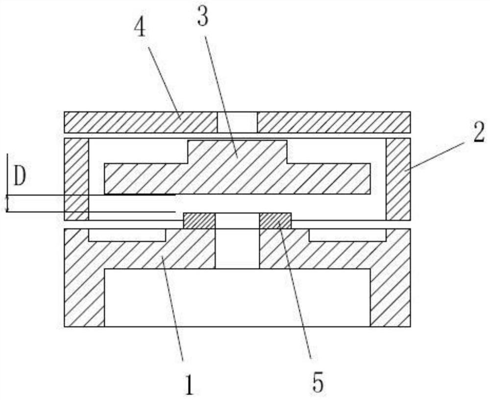
[0015] Such as Figure 1-2 As shown, a micro-flow valve control mechanism according to the present invention includes an electromagnetic coil, a base 1, a ring seat 2, a moving piece 3 and a shrapnel 4; the shrapnel 4 is located above the base 1, and the ring seat 2 and The moving piece 3 is located between the base 1 and the shrapnel 4, and both the moving piece 3 and the shrapnel 4 are of circular sheet structure; Clearance fit, so that the ring seat 2 can play a certain guiding role in the lifting of the moving piece 3; the base 1 is provided with a sealing ring 5 that cooperates with the moving piece 3, and the flow channel hole on the base 1 is located in the sealing ring The inner ring of 5, when the electromagnetic coil is not energized, the moving piece 3 falls on the sealing ring 5, and the flow channel hole on the base 1 is...


PUM


Abstract

The invention discloses a micro flow valve control mechanism. The micro flow valve control mechanism comprises an electromagnetic coil, a base, a ring seat, a rotor plate and an elastic sheet. The elastic sheet is located above the base. The ring seat and the rotor plate are located between the base and the elastic sheet. The rotor plate is located on the inner side of the ring seat. The base is provided with a sealing ring matched with the rotor plate. The electromagnetic coil is located on the upper side of the elastic sheet. A valve intake control structure is optimized. The ring seat achieves the guide effect on ascending and descending of the rotor plate to some extent. It is ensured that the rotor plate cannot defect in the intake process so that uniform air intake on an outer ring of the lower side of the rotor plate can be realized, and the operation stability of a solenoid valve is ensured. The electromagnetic coil generates upward suction force to the rotor plate, and the elastic sheet generates downward elastic force to the rotor plate; the height of the rotor plate can be slightly adjusted through current change of the coil, and then the opening degree of the valve is changed. The sealing ring on the base can ensure the airtightness of the valve after power-off of the coil.

Description

technical field [0001] The invention relates to a small flow valve control mechanism. Background technique [0002] Solenoid valve is the main part of fluid flow control. Solenoid valve generally attracts the magnetic core through electromagnetic coil, and controls the flow through the opening of the magnetic core. precision. Contents of the invention [0003] The object of the present invention is to provide a small flow valve control mechanism in order to overcome the deficiencies of the prior art. [0004] In order to achieve the above object, the technical solution adopted by the present invention is: a micro-flow valve control mechanism, including an electromagnetic coil, a base, a ring seat, a moving piece and a shrapnel; the shrapnel is located above the base, and the ring seat and the moving piece Located between the base and the shrapnel, the moving piece is located inside the ring seat, and the base is provided with a sealing ring that cooperates with the movin...

Claims


Application Information

Patent Timeline
Patent Type & Authority Applications(China)
IPC IPC(8): F16K31/06F16K1/36F16K1/32F16K27/02
CPCF16K31/0624F16K31/0675F16K1/36F16K1/32F16K27/029
Inventor 罗勇张仁钦陈红梅林正得叶辰朱晓明
Owner SUZHOU RAYONTECH TECH CO LTD
Why Eureka
Try Eureka