Supercharge Your Innovation With Domain-Expert AI Agents!

Valve mounting device

A technology for installing devices and valves, which is applied in the direction of workpiece clamping devices, pipe supports, pipes/pipe joints/fittings, etc., which can solve the problems of high work intensity of operators, achieve the effect of reducing work intensity and improving efficiency

Inactive Publication Date: 2020-09-04
郝赫
View PDF6 Cites 1 Cited by
  • Summary
  • Abstract
  • Description
  • Claims
  • Application Information

AI Technical Summary

Problems solved by technology

[0003] The purpose of the present invention is to provide a valve installation device to solve the problem that the existing device needs to use a large force to continuously lift the valve when installing the valve, and the operator's work intensity is relatively high

Method used


Image

  • Valve mounting device
  • Valve mounting device
  • Valve mounting device

Examples


Embodiment Construction

[0026] The following will clearly and completely describe the technical solutions in the embodiments of the present invention with reference to the accompanying drawings in the embodiments of the present invention. Obviously, the described embodiments are only some, not all, embodiments of the present invention.

[0027] In describing the present invention, it should be understood that the terms "upper", "lower", "front", "rear", "left", "right", "top", "bottom", "inner", " The orientation or positional relationship indicated by "outside", etc. is based on the orientation or positional relationship shown in the drawings, and is only for the convenience of describing the present invention and simplifying the description, rather than indicating or implying that the referred device or element must have a specific orientation, so as to Specific orientation configurations and operations, therefore, are not to be construed as limitations on the invention.

[0028] refer to Figure ...


PUM


Abstract

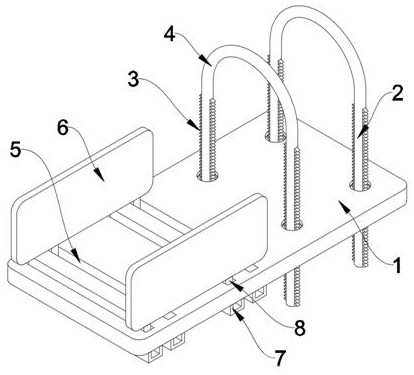
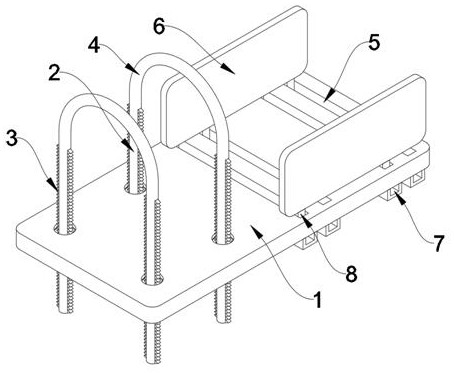
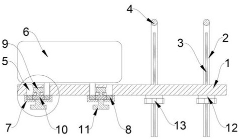
The invention relates to valve mounting devices, and discloses a valve mounting device. The valve mounting device comprises a bearing base. Four second rotating blocks are mounted at one end of the interior of the bearing base. Lifting rods are connected in the second rotating blocks in an insertion mode. Threaded strips are fixedly connected to the two sides of the lifting rods. A force bearing rod is connected between the two lifting rods in a welding mode. Two second sliding rails are fixedly arranged in the second rotating blocks. A first rotating block is rotatably connected to the otherend inside the bearing base. A meshing gear is welded and connected to the lower end of the first rotating block. According to the valve mounting device, the device is fixed to one end of a water pipethrough the force bearing rod, and then a valve is placed at the upper end of the device, so that an operator does not need to continuously lift the valve when mounting the valve, and the working intensity of the operator is greatly reduced. Moreover, the valve can be fixed to the center position of the device by just rotating a first rotating handle, and valve and water pipe calibration work iscompleted, so that the valve mounting efficiency is greatly improved.

Description

technical field [0001] The invention relates to a valve installation device, in particular to a valve installation device. Background technique [0002] Valves are the control components in the fluid delivery system. They have the functions of cut-off, adjustment, flow diversion, reverse flow prevention, pressure stabilization, flow diversion or overflow pressure relief. Valves used in fluid control systems range from the simplest cut-off valve to extremely complex The various valves used in the automatic control system have a wide variety of varieties and specifications. The valve installation device needs to be used for installation when the valve is installed, but the existing device needs to use a large force to continuously support the valve when installing the valve. For example, the work intensity of the operator is high, and the valve and water pipe need to be calibrated during installation, and the installation efficiency is poor. Therefore, we propose a valve insta...

Claims


Application Information

Patent Timeline
Patent Type & Authority Applications(China)
IPC IPC(8): F16M11/04F16M13/02F16L3/04
CPCB25B11/02B25B27/24F16L3/04F16M11/04F16M13/02
Inventor 郝赫
Owner 郝赫
Features
  • R&D
  • Intellectual Property
  • Life Sciences
  • Materials
  • Tech Scout
  • Unparalleled Data Quality
  • Higher Quality Content
  • 60% Fewer Hallucinations
Learn More