Liquid level stabilizing structure for controlling electrode water level tank in semi-immersed electrode boiler

An electrode boiler, semi-submerged technology, applied in the direction of electrode boilers, water supply control, steam boilers, etc., can solve the problems of different contact areas between electrodes and electrolyte solutions, the water surface of the inner cylinder is prone to waves, and reduce the service life of boilers. Increase heating effect, simple structure, reduce the effect of boiler shutdown

Inactive Publication Date: 2020-09-04
赵晓东
View PDF7 Cites 4 Cited by
  • Summary
  • Abstract
  • Description
  • Claims
  • Application Information

AI Technical Summary

Problems solved by technology

[0002] In the semi-submerged structure of the boiler in the prior art, the water replenishment port of the inner cylinder directly passes into the inner cylinder, which causes waves on the water surface of the inner cylinder, which causes the contact area between the electrode and the electrolyte solution to be different, which easily leads to an unbalanced three-phase current and zero Sequence current, when the zero-sequence current is too large, it will cause (high-voltage switchgear) to trip, causing the boiler to shut down
Frequent shutdown of the boiler affects the heating effect on the one hand, and reduces the service life of the boiler on the other hand

Method used


Image

  • Liquid level stabilizing structure for controlling electrode water level tank in semi-immersed electrode boiler
  • Liquid level stabilizing structure for controlling electrode water level tank in semi-immersed electrode boiler
  • Liquid level stabilizing structure for controlling electrode water level tank in semi-immersed electrode boiler

Examples


Embodiment

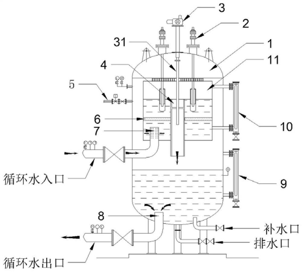
[0027] An embodiment, a structure for controlling the level stability of the electrode water level tank in a semi-submerged electrode boiler, see Figure 1-3 As shown, including the boiler body 1;

[0028] The inner upper end of the boiler body 1 is provided with a boiler inner cylinder 11 fixedly installed therewith;

[0029] The top of the boiler body 1 is provided with several electrodes 2, and the electrodes 2 extend through the part of the boiler body 1 to the inside of the boiler inner cylinder 11;

[0030] The middle end of the boiler inner cylinder 11 is provided with an overflow pipe 4 which is movable socketed therewith, the top end of the overflow pipe 4 communicates with the boiler inner cylinder 11, and the bottom end of the overflow pipe 4 communicates with the boiler body 1;

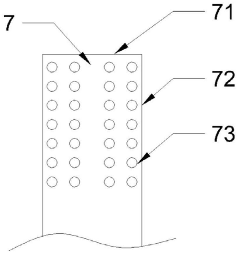
[0031] The bottom end of the boiler inner cylinder 11 is provided with a water inlet pipe 7 connected to it, and the boiler inner cylinder 11 above the water inlet pipe 7 is provided with...


PUM


Abstract

The invention discloses a liquid level stabilizing structure for controlling an electrode water level tank in a semi-immersed electrode boiler, and belongs to the technical field of boiler structures.The liquid level stabilizing structure can stably supplement water, reduce waves of the liquid level of an inner cylinder, and then reduce the occurrence rate of zero-sequence current, thereby improving the heat supply effect and prolonging the service life of a boiler, and is simple in structure and convenient to use. The liquid level stabilizing structure comprises a boiler body; a boiler innercylinder fixedly mounted with the boiler body is arranged at the upper end in the boiler body; multiple electrodes are arranged at the top end of the boiler; the electrodes penetrate through part ofthe boiler body to extend into the boiler inner cylinder; an overflow pipe movably connected with the boiler inner cylinder in a sleeving manner is arranged at the middle end of the boiler inner cylinder; the top end of the overflow pipe communicates with the boiler inner cylinder, and the bottom end of the overflow pipe communicates with the boiler body; a water inlet pipe communicating with theboiler inner cylinder is arranged at the bottom end of the boiler inner cylinder; a flow stabilizing separation plate for stabilizing the flowing rate is arranged on the boiler inner cylinder above the water inlet pipe; and a water outlet pipe matched with the water inlet pipe for use is arranged at the bottom end of the boiler body.

Description

technical field [0001] The invention relates to the technical field of boiler structures, in particular to a structure for controlling the stable liquid level of an electrode water level tank in a semi-submerged electrode boiler. Background technique [0002] In the semi-submerged structure of the boiler in the prior art, the water replenishment port of the inner cylinder directly passes into the inner cylinder, which causes waves on the water surface of the inner cylinder, which causes the contact area between the electrode and the electrolyte solution to be different, which easily leads to an unbalanced three-phase current and zero Sequence current, when the zero-sequence current is too large, it will cause (high voltage switchgear) to trip, causing the boiler to shut down. Frequent shutdown of the boiler affects the heating effect on the one hand, and reduces the service life of the boiler on the other hand. Contents of the invention [0003] The purpose of the present...

Claims


Application Information

Patent Timeline
Patent Type & Authority Applications(China)
IPC IPC(8): F22B1/30F22D5/06
CPCF22B1/30F22D5/06
Inventor 赵晓东赵伟光康丽婷
Owner 赵晓东
Why Eureka
Try Eureka