Method for assisting in testing large-maneuvering flight state antenna pattern by unmanned aerial vehicle

An antenna pattern and auxiliary test technology, which is applied in the direction of unmanned aircraft, antenna radiation pattern, aircraft, etc., can solve problems such as performance testing, and achieve the effect of avoiding excessive flying heights

Pending Publication Date: 2020-09-04
10TH RES INST OF CETC
View PDF6 Cites 2 Cited by
  • Summary
  • Abstract
  • Description
  • Claims
  • Application Information

AI Technical Summary

Problems solved by technology

[0004] The present invention is aimed at the requirement of large pitch angles in the test and verification of the antenna of the whole machine at present, and verifies the radio frequency link, radio frequency compatibility, radio frequency stealth and other wireless technical indicators related to the antenna under large maneuvering conditions. The performance test problem of the airborne antenna under the condition of large m

Method used


Image

  • Method for assisting in testing large-maneuvering flight state antenna pattern by unmanned aerial vehicle
  • Method for assisting in testing large-maneuvering flight state antenna pattern by unmanned aerial vehicle
  • Method for assisting in testing large-maneuvering flight state antenna pattern by unmanned aerial vehicle

Examples


Embodiment 1

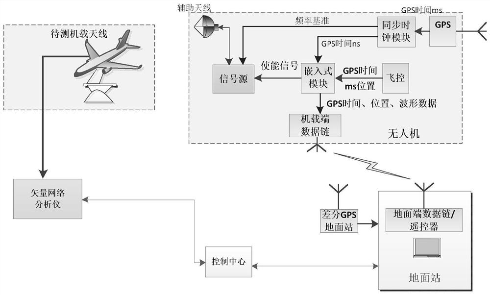
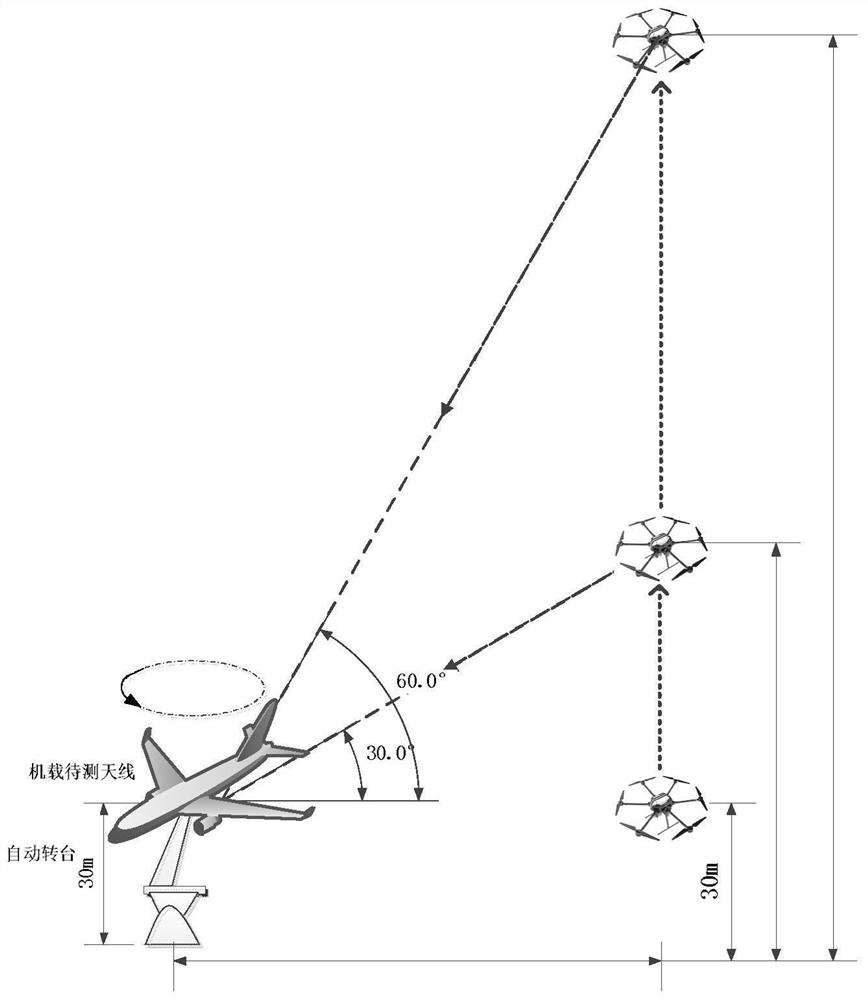
[0016] refer to figure 2 . The UAV uses an omnidirectional antenna suspended under the UAV. The ground UAV measurement and control terminal controls the omnidirectional antenna of the UAV’s hovering height and position and the UAV auxiliary antenna as an auxiliary test terminal. The ground control terminal controls the UAV. Human-machine transmission frequency and signal strength, test the direction diagram of the airborne antenna communication of the UAV to be tested.

[0017] The airborne antenna to be tested is installed on the airborne platform, and the test turntable rotates around the axis. The airborne antenna to be tested is connected to the vector grid. It moves on a circle centered on the rotation axis of the table. The ground UAV measurement and control terminal controls the hovering height and position of the UAV. The ground station receives the signals emitted by the auxiliary antenna of the UAV auxiliary terminal at various angles, and the ground station receiv...

Embodiment 2

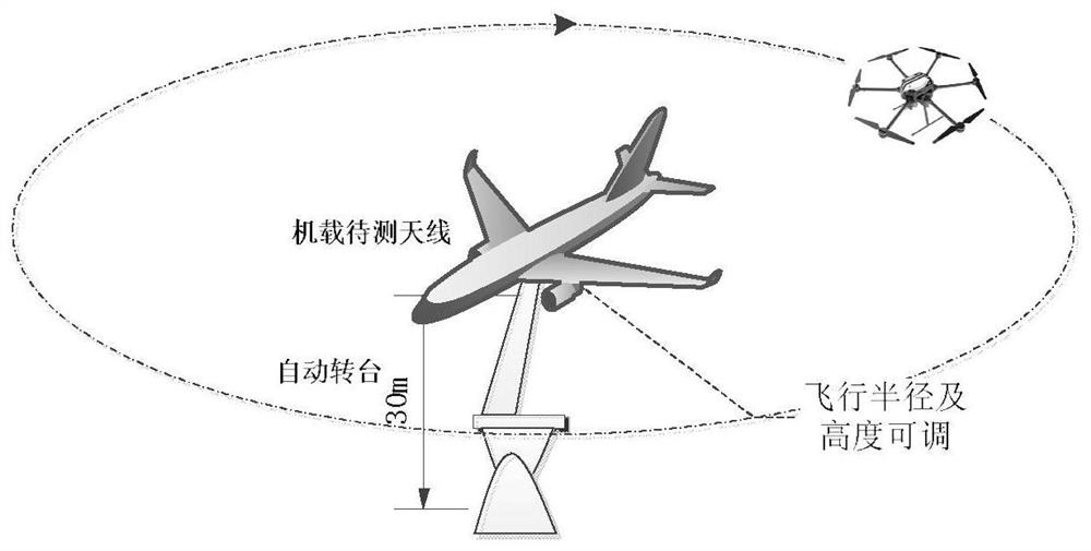
[0021] refer to image 3 . The unmanned aerial vehicle adopts the way of flying around, and the airborne test terminal of the ground station adopts a fixed airborne antenna to be tested. According to the radius satisfying the far-field condition, the drone is set to fly around at a fixed radius with the turntable as the center. Man-machine flight height, auxiliary antenna transmission frequency and transmission signal strength, while controlling the drone loaded with signal source to fly around the receiving antenna, and by adjusting the flight height and flight radius of the drone, the antenna pattern test of the whole antenna in different angles is realized .


PUM


Abstract

The invention discloses a method for assisting in testing a large-maneuvering flight state antenna pattern by an unmanned aerial vehicle, and aims to provide a test method for solving the problems ofradio frequency link and radio frequency compatible wireless related to an antenna of an outfield aircraft under a large maneuvering condition. The method is realized through the following technical scheme: by utilizing a differential GPS ground mobile station built by an unmanned aerial vehicle, an airborne GPS antenna of the unmanned aerial vehicle sends a frequency reference and GPS time to anembedded module and a signal source through a synchronous clock module; the embedded module sends GPS time and position data to the signal source and the airborne data link terminal according to an enable signal generated according to GPS time and position input by an airborne flight control system of the auxiliary unmanned aerial vehicle; and the ground terminal remotely controls the waveform ofa signal emitted by the auxiliary unmanned aerial vehicle, the unmanned aerial vehicle changes height, hovers or flies around according to the test requirements, the flight strategy of the auxiliary unmanned aerial vehicle is flexibly adjusted through the test turntable of the ground station, and the directional diagram test of the to-be-tested airborne antenna at different pitch angles and azimuth angles is finished.

Description

technical field [0001] The present invention relates to the technical field of antenna testing, and more specifically relates to an unmanned aerial vehicle-assisted testing method that can be applied to verify the ultrashort-wave antenna pattern of a complete machine in the outfield of a large aircraft-mounted platform. Background technique [0002] Communications, radar, navigation, radio, television and other radio technology equipment all transmit information through radio waves, and all require the transmission and reception of radio waves. As an important part of the airborne radio frequency sensor system, the antenna pattern is an important index of the antenna, and its test verification has become an important work content in the development of the current engineering model. In order to achieve the best communication effect, the antenna must have a certain directionality, high conversion efficiency, and a frequency bandwidth that meets the requirements of the system. ...

Claims


Application Information

Patent Timeline
IPC IPC(8): G01R29/10
CPCG01R29/105B64U2101/00
Inventor 芮锡杨斌李亚军李铂高鹏程郭晨钟志浩
Owner 10TH RES INST OF CETC
Why Eureka
Try Eureka