Airborne ultra-short wave antenna pattern UAV auxiliary test system

An antenna pattern and auxiliary test technology, which is applied to antenna radiation patterns, measuring devices, measuring electrical variables, etc., can solve problems such as performance testing, and achieve the effect of avoiding excessive flying heights

Inactive Publication Date: 2020-11-17
10TH RES INST OF CETC
View PDF6 Cites 1 Cited by
  • Summary
  • Abstract
  • Description
  • Claims
  • Application Information

AI Technical Summary

Problems solved by technology

[0004] The present invention is aimed at the requirement of a large pitch angle for the current antenna test and verification of the whole machine, and verifies wireless technical indicators such as radio frequency link, radio frequency compatibility, and radio frequency stealth related to the antenna under large maneuvering conditions. The performance test problem of the airborne antenna under the condition of large ma...

Method used


Image

  • Airborne ultra-short wave antenna pattern UAV auxiliary test system
  • Airborne ultra-short wave antenna pattern UAV auxiliary test system
  • Airborne ultra-short wave antenna pattern UAV auxiliary test system

Examples


Embodiment 1

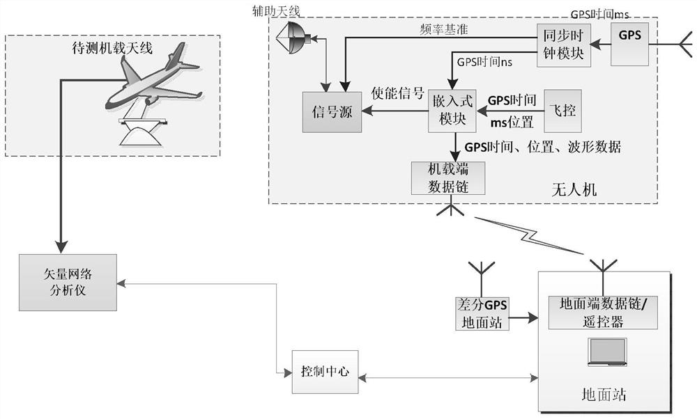
[0016] refer to figure 2 . The auxiliary antenna is suspended on the lower part of the UAV with an omnidirectional antenna. The ground station terminal controls the hovering height and position of the auxiliary UAV through the measurement and control terminal of the ground UAV according to the hovering method adopted by the auxiliary UAV, and serves as an auxiliary test terminal. Antenna, control the transmission frequency and signal strength of the auxiliary UAV through the ground control terminal, and test the communication pattern of the airborne antenna to be tested.

[0017] The airborne antenna to be tested is connected with the vector network, installed on the airborne platform, bypasses the rotation axis of the rotation center and is perpendicular to the table surface, rotates around the axis of the automatic turntable to make a circular motion, and receives and assists the UAV side to assist the antenna to transmit signal of. The ground UAV measurement and control ...

Embodiment 2

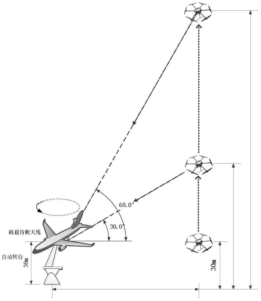
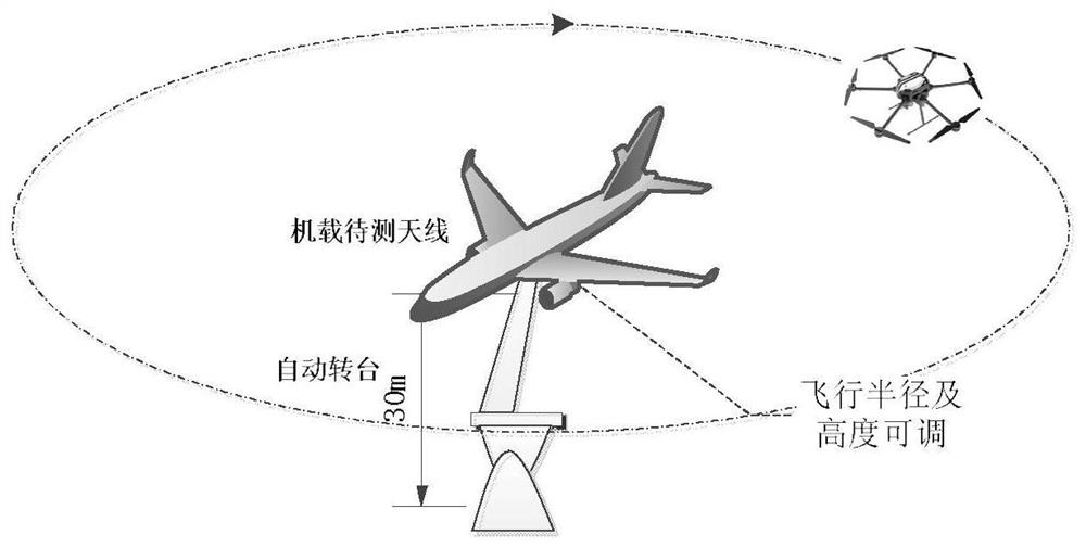
[0023] refer to image 3 . The auxiliary UAV adopts the flying around method. The airborne terminal of the ground station terminal to be tested adopts a fixed receiving antenna. According to the flight radius that meets the far-field conditions, the automatic turntable is used as the center to set the auxiliary UAV to fly around the tested aircraft according to the fixed flight radius, and the auxiliary UAV is controlled. The flight height of the man-machine, the transmission frequency of the auxiliary antenna and the strength of the transmission signal, while controlling the flight of the loading signal source around the receiving antenna, by adjusting the flight height and flight radius of the auxiliary UAV, the different angle domain antennas of the whole antenna of the UAV under test can be realized Orientation test.


PUM


Abstract

The invention discloses an airborne ultra-short wave antenna pattern UAV auxiliary test system, and aims to provide a test method for solving the problem of radio frequency link and radio frequency compatible wireless related to an antenna of an outfield aircraft under a large maneuvering condition. According to the technical scheme of the invention, the method comprises the steps: according to adifferential GPS ground mobile station built by the unmanned plane, an airborne GPS antenna of an unmanned plane is used to transmits a frequency reference and GPS time to an embedded module and a signal source through a synchronous clock module; the embedded module sends an enable signal generated according to GPS time and position input by an airborne flight control system of the auxiliary unmanned aerial vehicle to the signal source and the airborne data link terminal, the ground terminal remotely controls the waveform of the signal emitted by the auxiliary unmanned aerial vehicle, and hovers or flies around according to the change height of the tested unmanned aerial vehicle; then the flight strategy of the auxiliary unmanned aerial vehicle is flexibly adjusted through the test turntable of the ground station terminal, and therefore, the directional diagram test of the to-be-tested airborne antenna at different pitch angles and azimuth angles is completed.

Description

technical field [0001] The present invention relates to the technical field of antenna testing, and more specifically relates to a method that can be applied to the field antenna test and verification of a large aircraft-mounted platform, using radio remote control equipment and a self-provided program control device to control the UAV, and realize the ultrashort wave antenna pattern test. Background technique [0002] Communications, radar, navigation, radio, television and other radio technology equipment all transmit information through radio waves, and all require the transmission and reception of radio waves. As an important part of the airborne radio frequency sensor system, the antenna pattern is an important index of the antenna, and its test verification has become an important work content in the development of the current engineering model. In order to achieve the best communication effect, the antenna must have a certain directionality, high conversion efficienc...

Claims


Application Information

Patent Timeline
IPC IPC(8): G01R29/10G01R29/08
CPCG01R29/105G01R29/0892G01R29/0871
Inventor 芮锡杨斌李亚军李铂高鹏程郭晨钟志浩
Owner 10TH RES INST OF CETC
Why Eureka
Try Eureka