Patch type fuse applied to switching power supply

A technology of switching power supply and fuse, which is applied in the direction of circuits, electrical components, emergency protection devices, etc., can solve the problems of not being able to fuse quickly and cleanly, affect the life of PCB, waste PCB space, etc., achieve fast and clean fusing ability, and improve service life , Reduce the effect of application space

Pending Publication Date: 2020-09-04
TANGSHAN HANGYU ELECTRIC POWER & ELECTRONICS EQUIP CO LTD
View PDF0 Cites 0 Cited by
  • Summary
  • Abstract
  • Description
  • Claims
  • Application Information

AI Technical Summary

Problems solved by technology

However, the existing chip fuses can only have one kind of fuse and only one fusing current. If you want to use it in parallel or want to multi-level fusing, you need to connect multiple fuses in parallel or combine multiple fuses to form a multi-level fusing. Not only It wastes PCB space and delays time. At the same time, due to material and space limitations, the existing fuse may not be able to fuse quickly and cleanly.
In addition, once the existing fuse is damaged, it can only be considered to replace the entire fuse, which is not only troublesome, but also affects the life of the PCB

Method used


Image

  • Patch type fuse applied to switching power supply
  • Patch type fuse applied to switching power supply
  • Patch type fuse applied to switching power supply

Examples


Embodiment Construction

[0037] The present invention will be further described in detail below with reference to the accompanying drawings and embodiments.

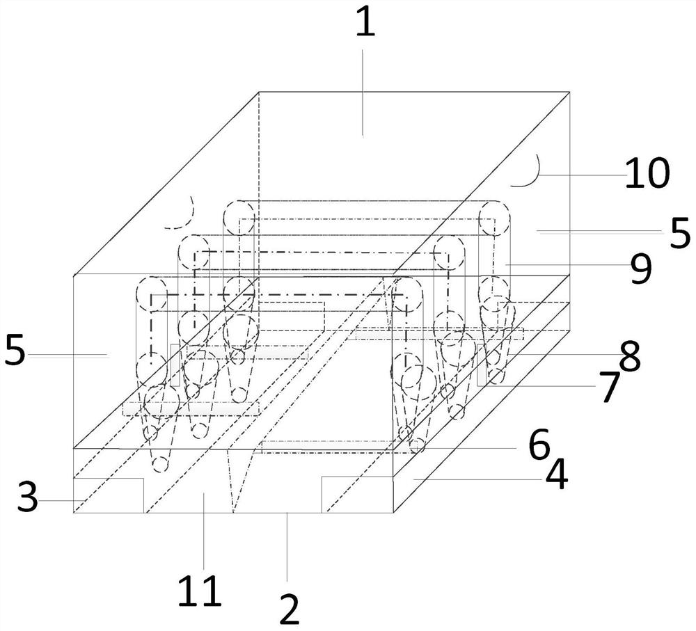
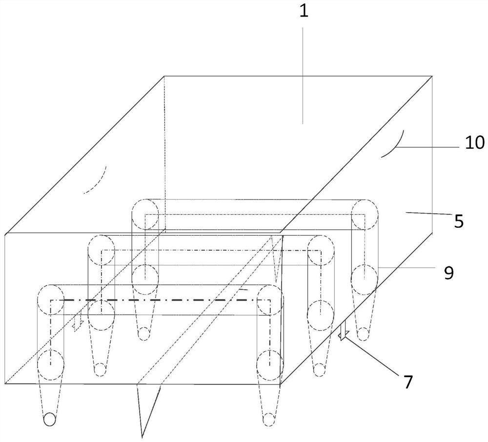
[0038] like figure 1 As shown, a chip fuse applied to a switching power supply includes a fuse replacement part 5 and a fuse welding part 11; There are several fuse main bodies 9, which are fixedly installed in the inner cavity of the upper base plate 1; The buckle of the lock 7 is connected to the lower part of the upper substrate 1; The first end surface electrode 3 and the second end surface electrode 4 are respectively fixed on the left and right ends of the lower substrate 2, and are fully or partially exposed to the lower substrate 2; the metal slot 8 is arranged in the lower substrate 2. The upper part of the lower base plate 2, and the number and size are corresponding to the fuse body 9, which is used for inserting the slot body insertion part of the fuse body 9; the card slot of the locking buckle 7 is connected to the lower base pla...


PUM


Abstract

The invention relates to a patch type fuse applied to a switching power supply. The fuse comprises a fuse replacing part and a fuse welding part. The fuse replacing part comprises an upper substrate,a fuse main body and a buckle of a lock catch. The fuse main body is fixedly installed in an inner cavity of the upper substrate. The slot body plugging part of the fuse main body is exposed out of the lower part of the upper substrate. A buckle of the lock catch is connected to the lower part of the upper substrate. The fuse welding part comprises a lower substrate, a first end surface electrode,a second end surface electrode, a metal slot and a clamping slot of a lock catch. The first end surface electrode and the second end surface electrode are respectively fixed at left and right ends ofthe lower substrate. The metal slot is formed in the upper part of the lower substrate and is used for plugging the slot body plugging part. The clamping groove of the lock catch is connected to theupper portion of the lower base plate. The fuse has quick and clean fusing capability, and can meet the requirement of a researcher on multiple fuses or the requirement of multi-stage fusing for parallel connection of different fusing currents.

Description

technical field [0001] The invention relates to the technical field of fuses, in particular to a chip fuse applied to a switching power supply. Background technique [0002] With the development of power electronics technology, power modules have been widely used in various fields, and switching power supplies have gradually replaced linear power supplies and become mainstream power supplies. The power of the equipment is mainly provided by the switching power supply. One of the performance indicators of the switching power supply is the use of fuses. [0003] Fuses are commonly used electrical components that play a protective role in circuits. Generally, when the fuse circuit is overloaded, the fuse is heated by the fuse current to quickly fuse the fuse, thereby disconnecting the circuit to achieve circuit protection. The surface mount overcurrent fuse has the characteristics of small size and convenient installation. When the current in the circuit exceeds the safe valu...

Claims


Application Information

Patent Timeline
Patent Type & Authority Applications(China)
IPC IPC(8): H01H85/041H01H85/05H01H85/12H01H85/22H01H85/38
CPCH01H85/0411H01H85/05H01H85/12H01H85/22H01H85/38H01H2085/0412H01H2085/0414
Inventor 蒋明明刘凤涛
Owner TANGSHAN HANGYU ELECTRIC POWER & ELECTRONICS EQUIP CO LTD
Why Eureka
Try Eureka