Up-conversion piezoelectric-electromagnetic energy harvesting device

An electromagnetic and energy-harvesting technology, applied in piezoelectric effect/electrostrictive or magnetostrictive motors, generators/motors, electrical components, etc. Problems such as low vibration frequency can achieve the effect of improving power generation efficiency, increasing excitation frequency, and increasing output power

Active Publication Date: 2020-09-04
BEIJING INSTITUTE OF TECHNOLOGYGY
View PDF5 Cites 1 Cited by
  • Summary
  • Abstract
  • Description
  • Claims
  • Application Information

AI Technical Summary

Problems solved by technology

In some conventional vibration environments, the vibration frequency is low, it is difficult to reach the resonance frequency of the piezoelectric sheet, and its output power is also low
The conventional piezoelectric up-conversion structure generally adopts a cantilever beam structure, including a driving beam with low-frequency vibration and a piezoelectric beam with high-frequency vibration. This structure uses the collision between the driving beam and the piezoelectric beam to increase the excitation frequency. To a certain extent, the excitation environment that the energy harvester is suitable for can be reduced, but the excitation frequency that the overall structure can adapt to is still very large. Technical problems such as low efficiency, heavy wear, and high difficulty in assembly

Method used


Image

  • Up-conversion piezoelectric-electromagnetic energy harvesting device
  • Up-conversion piezoelectric-electromagnetic energy harvesting device
  • Up-conversion piezoelectric-electromagnetic energy harvesting device

Examples


Embodiment Construction

[0030] In order to further illustrate the technical means and effects taken by the present invention to achieve the expected purpose, so that the advantages and characteristics of the present invention can be more easily understood by those skilled in the art, the specific implementation methods, structural features and other aspects of the present invention will be described in conjunction with the accompanying drawings and examples. The efficacy is described in detail below.

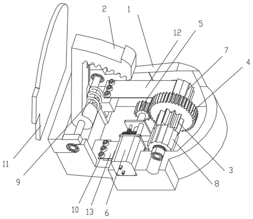
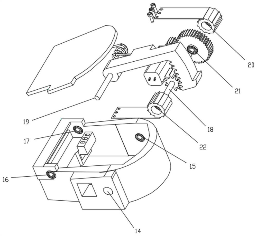
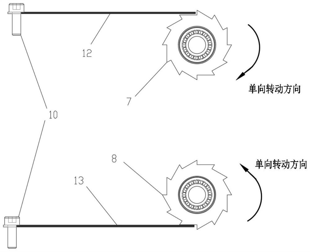
[0031] Such as figure 1 , 2 As shown, a frequency-up piezoelectric-electromagnetic energy harvesting device disclosed in this embodiment consists of a housing 1, an arc rack 2, a primary gear 3, a secondary gear 4, a speed-up gear set 5, a generator 6, Forward rotation ratchet 7, reverse rotation ratchet 8, return spring 9, piezoelectric sheet fastening screw 10, partition 11, piezoelectric sheet one 12, piezoelectric sheet two 13, two-way bearing one 14, two-way bearing two 15, Two-way bearing three...


PUM


Abstract

The invention discloses an up-conversion piezoelectric-electromagnetic energy harvesting device, and belongs to the technical field of power generation. Mechanical vibration energy can be converted into electric energy to be stored in an up-conversion piezoelectric-electromagnetic energy harvesting mode, power supply to a microelectronic device is achieved, and the device has the advantages of being free of pollution, large in energy density, high in reliability and the like. Energy is recovered when the heel is pressed down and lifted up, a first piezoelectric plate and a generator output energy in the pressing down process, and a second piezoelectric plate outputs energy when the heel is lifted. According to the invention, a ratchet wheel structure is adopted to perform up-conversion onthe piezoelectric plate, the excitation frequency of the piezoelectric plate is improved, and the output power of piezoelectric energy harvesting is improved. The rotating speed of a gear during pressing is increased through a gear speed increasing module, and the power generation efficiency of the electromagnetic energy harvesting module is improved. The adopted one-way bearing can reduce the resistance in the treading process and the return process to the maximum extent, and the friction to a shaft is reduced to the maximum extent when two ratchet wheels and the one-way bearing in the hole of a secondary gear move in the non-working direction.

Description

technical field [0001] The invention relates to a frequency-up piezoelectric-electromagnetic energy harvesting device, which belongs to the technical field of power generation. Background technique [0002] At present, the power supply components of commonly used electronic appliances are generally chemical batteries, which have limited energy storage and need to be replaced regularly, resulting in high manpower and material costs. With the development of some low-power sensors and micro-miniature electronic devices, it has become a more reasonable and reliable solution to use energy harvesting in the vibration environment where these sensing devices are located. By designing a reasonable and reliable energy harvesting structure, the vibration environment Convert mechanical energy into electrical energy, store or rectify it as a power source for tiny electronic devices. For electromagnetic energy harvesters, increasing the rate of change of magnetic flux is an effective way...

Claims


Application Information

Patent Timeline
Patent Type & Authority Applications(China)
IPC IPC(8): H02N2/18
CPCH02N2/186
Inventor 郭胜凯高世桥金磊尹作宗李泽章
Owner BEIJING INSTITUTE OF TECHNOLOGYGY
Why Eureka
Try Eureka