
Chemical processing waste gas purification tower

A technology for chemical processing and purification towers, applied in chemical instruments and methods, dispersed particle filtration, dispersed particle separation, etc., can solve the problems of discounted purification effect, dusty, impurity, uneven distribution of gas and liquid, etc., and achieve enhanced lateral movement ability , The contact area is increased, and the effect of enhancing the purification effect

Inactive Publication Date: 2020-09-08
杨君梅
View PDF0 Cites 1 Cited by
  • Summary
  • Abstract
  • Description
  • Claims
  • Application Information

AI Technical Summary

Problems solved by technology

[0004] In order to make up for the deficiencies of the existing technology, solve the problem that the packing tower in the prior art is not evenly contacted with the exhaust gas when the chemical exhaust gas is purified, and in the long-term exhaust gas treatment process, the inner wall of the tower is easy to adhere to more dust, Impurities, thereby causing corrosion to the purification tower and affecting the purification effect, a chemical processing waste gas purification tower proposed by the present invention
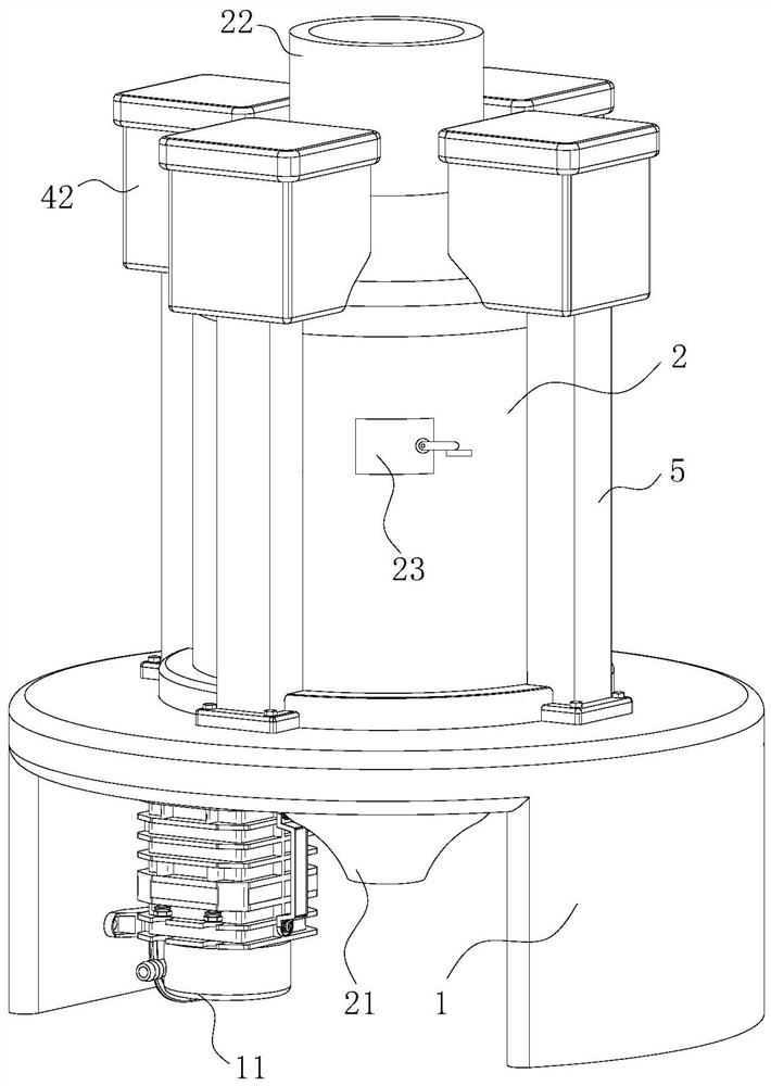
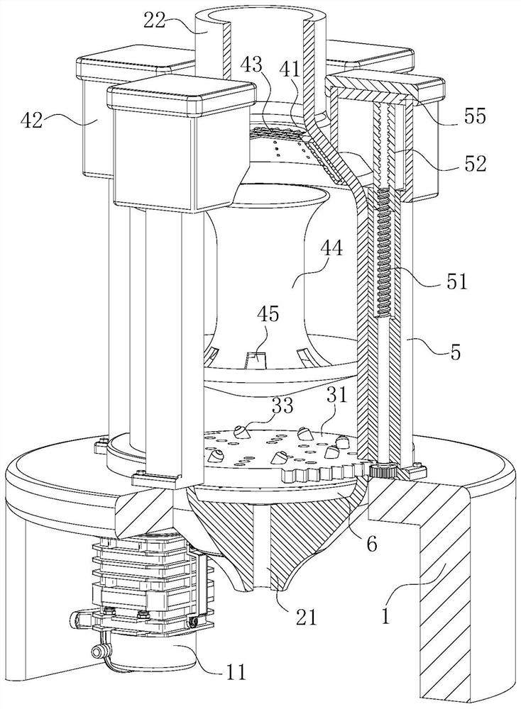
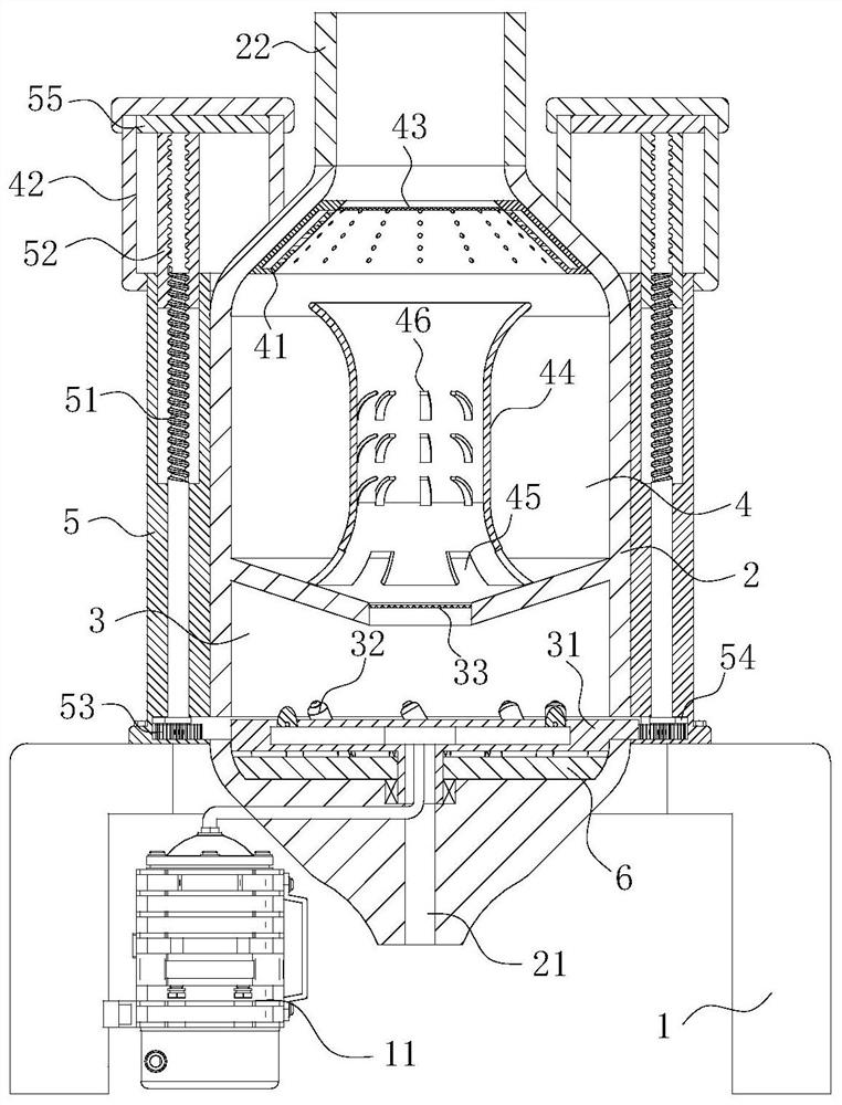
[0006] In the prior art, for exhaust gas purification, most of the purification agents are used to adsorb harmful components in the exhaust gas, thereby purifying the exhaust gas components and effectively reducing the pollution to the environment when the exhaust gas is discharged into the air. Existing exhaust gas purification towers are roughly divided into Plate tower or packed tower, the structure of the plate tower is relatively complicated, it is more troublesome to install, it requires high installation accuracy, and it is easy to deviate due to the installation angle, which greatly reduces the purification effect, while the structure of the packed tower itself is relatively simple. The exhaust gas purification effect is better, but the packed tower also has uneven distribution of gas and liquid, which leads to incomplete contact between the purifying agent and the exhaust gas, and thus makes the purification effect poor. At this time, the air compressor is started, and the air compressor compresses the outside air and sends it to the first cavity. They are designed to be inclined along the circumferential direction of the rotating disk, and the rotating disk rotates at a constant speed under the action of the reaction force of the jet airflow. Since a stable airflow is formed in the first cavity and the connection between the first cavity and the intake pipe, the airflow is flowing At the same time, it can adsorb the exhaust gas in the intake pipe, so that the compressed air mixed with the exhaust gas delivered by the air compressor is sprayed into the coarse filter cavity through the injection pipe. The exhaust gas is cooled rapidly. As time goes by, the air pressure in the coarse filter chamber gradually rises, and the airflow enters the adsorption chamber along the coarse filter chamber and the opening of the adsorption chamber. During the rising process, the airflow produces a negative impact on the catalytic balls filled in the adsorption chamber. The impact of upward movement, while the air flow rises upwards, the purifier in the liquid storage tank enters the spray ring through the conduit under the action of pressure, and drops on the accumulated catalytic balls through the through holes opened on the surface of the spray ring. On the top, due to the inclined design of the spray ring, the purifying agent drips down evenly, and at the same time, when the purifying agent falls down along the surface of the catalytic ball, it adheres to the surface of the catalytic ball to form a uniform liquid film. The slit of the catalytic ball is in full contact with the liquid film during the advancement process, so that the exhaust gas components contained in the air flow are quickly purified, and the use of the catalytic ball with the design of the spray ring makes the distribution between the purifying agent and the exhaust gas more uniform, thereby The purification process of exhaust gas is faster and more convenient. At the same time, the purification agent sprayed by the spray ring gradually drips down and gathers on the rotating disk. When the exhaust gas is sprayed out through the injection pipe, it can further cool down the exhaust gas.

Method used


Image

  • Chemical processing waste gas purification tower
  • Chemical processing waste gas purification tower
  • Chemical processing waste gas purification tower

Examples


Embodiment approach

[0025] As an embodiment of the present invention, a booster tube 5 is fixedly connected to the outside of the housing; the booster tube 5 is designed to extend into the liquid storage tank 42; the booster tube 5 is rotatably connected to a lead screw 51 The thread on the screw 51 is engaged with a sliding block 52; the screw 51 is located at the bottom of the booster tube 5 and is sleeved with a rotating wheel 53; the side of the rotating disc 31 is half straight toothed and half smooth; The lead screw 51 is located above the rotating wheel 53 and is wound with an elastic rope 54; the sliding block 52 extends to the top of the inner cavity of the liquid storage tank 42; the sliding block 52 is located at one end of the liquid storage tank 42 and is fixedly connected with an extruding plate 55; The purifying agent in the second cavity in the spray ring 41 drips downward under the action of gravity and hydraulic pressure difference, and the droplet particles are relatively large,...


PUM


Abstract

The invention belongs to the technical field of waste gas treatment accessory devices, and particularly relates to a chemical processing waste gas purification tower, which comprises a support frame,a tower body and an air compressor. The tower body is fixedly connected to the upper surface of the support frame; a rough filtration cavity and an adsorption cavity are formed in the tower body; thetower body is provided with an air inlet pipe below the rough filtration cavity; the air inlet pipe is used for connecting a waste gas generation device; the air inlet pipe is communicated with the rough filtration cavity; the joint of the rough filtration cavity and the air inlet pipe is rotatably connected to a rotating disc through a bearing; a first cavity is formed in the rotating disc; the first cavity is designed in a * shape; the first cavity is communicated with the air inlet pipe; evenly-distributed injection pipes are installed at the end, away from the air inlet pipe, of the rotating disc. By arranging the air compressor, the rough filtration cavity and the adsorption cavity, the contact area between rising waste gas and a purifying agent is remarkably increased through a purifying agent liquid film formed on the surface of a catalytic ball, and then the purification effect on the waste gas is effectively enhanced.

Description

technical field [0001] The invention belongs to the technical field of waste gas treatment attachments, in particular to a chemical processing waste gas purification tower. Background technique [0002] In the prior art, for exhaust gas purification, most of the purification agents are used to adsorb harmful components in the exhaust gas, thereby purifying the exhaust gas components and effectively reducing the pollution to the environment when the exhaust gas is discharged into the air. Existing exhaust gas purification towers are roughly divided into Plate tower or packed tower, the structure of the plate tower is relatively complicated, it is more troublesome to install, it requires high installation accuracy, and it is easy to deviate due to the installation angle, which greatly reduces the purification effect, while the structure of the packed tower itself is relatively simple. The exhaust gas purification effect is better, but the packed tower also has uneven distribut...

Claims


Application Information

Patent Timeline
Patent Type & Authority Applications(China)
IPC IPC(8): B01D53/86B01D53/04B01D46/12
CPCB01D46/12B01D53/04B01D53/86B01D2253/102
Inventor 杨君梅尹秀兰王为迪
Owner 杨君梅
Learn More