Industrial ore collecting and crushing device
A crushing device and ore technology, applied in transportation and packaging, conveyors, grain processing, etc., can solve the problems of low efficiency, difficult to crush ore, low production efficiency, etc., and achieve the effect of improving crushing efficiency
- Summary
- Abstract
- Description
- Claims
- Application Information
AI Technical Summary
Problems solved by technology
Method used
Image

Examples
specific Embodiment approach 1
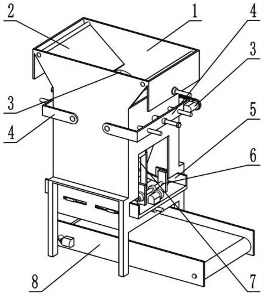
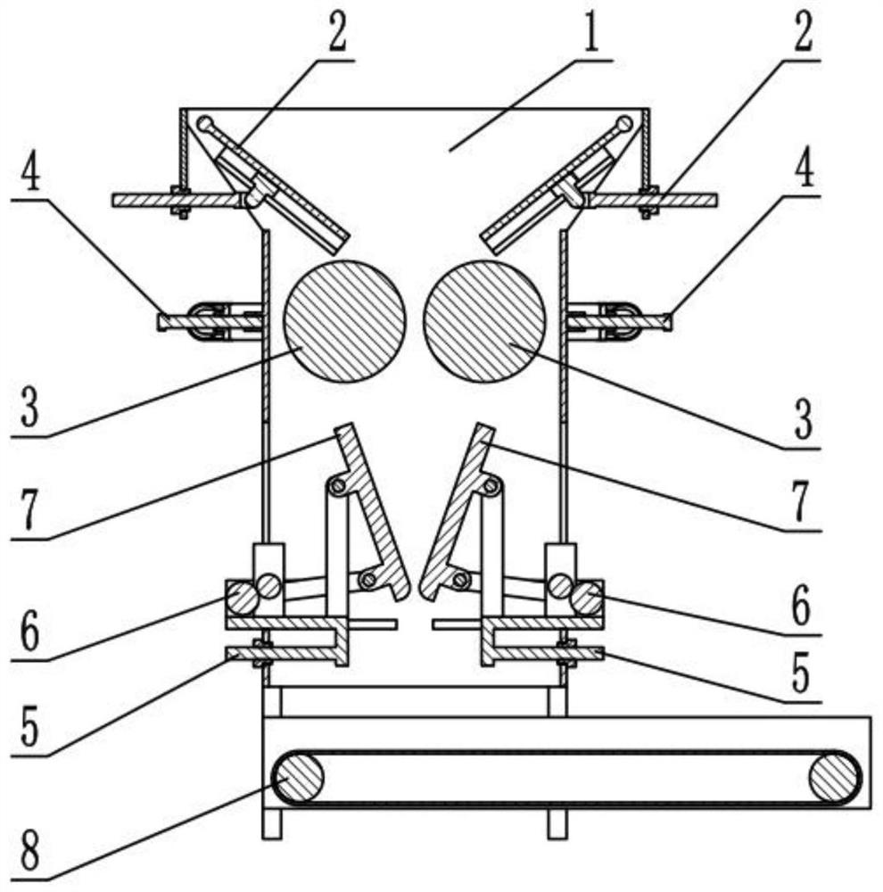
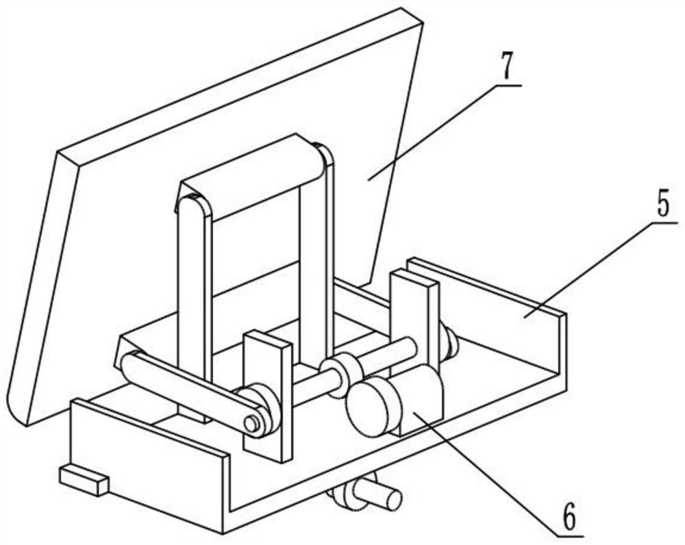
[0029] Such as Figure 1-11 As shown, an industrial ore collection and crushing device includes a crushing box 1, a blocking mechanism 2, a nip roller crushing mechanism 3, a nip roller adjustment mechanism 4, a moving frame 5, a plate clamp power mechanism 6, a plate clamp frame 7 and a conveyor Mechanism 8. There are two blocking mechanisms 2, and the two blocking mechanisms 2 are symmetrically connected to the upper end of the crushing box 1. The pinch roller crushing mechanism 3 is provided with two, and the two pinch rollers The crushing mechanism 3 is slidingly connected front and rear symmetrically in the crushing box 1. There are two nip roller adjustment mechanisms 4, and the two nip roller adjusting mechanisms 4 are symmetrically slidingly connected at the front and rear ends of the crushing box 1. The nip roller crushing mechanism 3 is respectively connected to the two nip roller adjustment mechanisms 4 in rotation, and the two moving frames 5 are provided with two,...
specific Embodiment approach 2
[0032] Such as Figure 1-11 As shown, the crushing box 1 includes a crushing frame 1-1, a hollow opening 1-2, a sliding hole 1-3, a sliding column 1-4, a fixing pipe 1-5, a fixing plate 1-6, and a side plate 1 -7, upper sliding hole 1-8 and support leg 1-9, the front and rear sides of the lower part of the crushing frame 1-1 are provided with hollowed out openings 1-2, and the lower sliding hole 1-3 and the upper sliding hole 1-8 are all provided with Two, two sliding holes 1-3 and two upper sliding holes 1-8 all run through the crushing frame 1-1 left and right, and the two sliding holes 1-3 are located below the two upper sliding holes 1-8, and the crushing frame 1 The front and rear sides of -1 are fixedly connected with two sliding columns 1-4, and there are two fixed pipes 1-5, and the two fixed pipes 1-5 are respectively fixedly connected to the front and rear sides of the crushing frame 1-1, and the crushing The left and right sides of the upper end of the frame 1-1 ar...
specific Embodiment approach 3
[0034] Such as Figure 1-11 As shown, the baffle mechanism 2 includes a baffle plate 2-1, a baffle shaft 2-2, a sliding seat 2-3, a slider 2-4, a threaded sleeve I2-5, a rotary block 2-6 and a threaded Rod Ⅰ 2-7, grid baffle plate 2-1 is fixedly connected on the baffle shaft 2-2, the outer end surface of grid baffle plate 2-1 is fixedly connected with sliding seat 2-3, and the inner sliding connection of sliding seat 2-3 has The slider 2-4, the slider 2-4 is rotatably connected with the rotary block 2-6, the rotary block 2-6 is fixedly connected with the threaded rod I2-7, and the threaded rod I2-7 is threadedly connected with the threaded sleeve I2- 5. There are two blocking mechanisms 2, and the two blocking mechanisms 2 are arranged symmetrically. The two baffle shafts 2-2 are respectively connected to the front and rear ends of the two side plates 1-7 in rotation. The two threaded Set I 2-5 is respectively rotatably connected to two fixed plates 1-6;
[0035] Turn the th...
PUM
 Abstract
Description
Claims
Application Information
 - R&D
- Intellectual Property
- Life Sciences
- Materials
- Tech Scout
- Unparalleled Data Quality
- Higher Quality Content
- 60% Fewer Hallucinations
Browse by: Latest US Patents, China's latest patents, Technical Efficacy Thesaurus, Application Domain, Technology Topic, Popular Technical Reports.
© 2025 PatSnap. All rights reserved.Legal|Privacy policy|Modern Slavery Act Transparency Statement|Sitemap|About US| Contact US: help@patsnap.com