Using method of electrostatic dust collection device for construction site

A dust removal device and construction site technology, applied in the direction of electrostatic separation, electrostatic effect separation, external electrostatic separator, etc., can solve problems such as respiratory diseases, occupation, and large volume of dust collectors, and achieve the effect of good ability to absorb dust and dust

Active Publication Date: 2020-09-08
山东一滕建设集团有限公司
View PDF17 Cites 1 Cited by
  • Summary
  • Abstract
  • Description
  • Claims
  • Application Information

AI Technical Summary

Problems solved by technology

[0002] Due to the characteristics of the construction industry, the air near the construction site will be filled with a lot of dust and other impurities. This is the most common problem in the construction industry. Serious impact, inhalation will cause various respiratory diseases, and once the dust enters the construction machinery, it will shorten the service life of the machine, so in consideration of safety itself, coupled with the current high requirements for environmental protection in the country, construction A lot of dust removal equipment is needed on the construction site to purify the air and remove dust and dust
[0003] However, at present, the traditional dust collector adopts a filter cartridge dust collector. After a period of use of this kind of dust collector, the filter cartridge is prone to clogging, resulting in a significant decline in dust removal effect. Moreover, this type of dust collector has a large volume and will occupy a large area. The construction space is not suitable for construction sites; at the same time, the structure of the emerging electrostatic precipitator is too complicated, and frequent maintenance is required. The maintenance cost is high during use, and it needs to consume a lot of electricity, which is not environmentally friendly.

Method used


Image

  • Using method of electrostatic dust collection device for construction site
  • Using method of electrostatic dust collection device for construction site
  • Using method of electrostatic dust collection device for construction site

Examples


Embodiment Construction

[0021] The following will clearly and completely describe the technical solutions in the embodiments of the present invention with reference to the accompanying drawings in the embodiments of the present invention. Obviously, the described embodiments are only some, not all, embodiments of the present invention.

[0022] In describing the present invention, it should be understood that the terms "upper", "lower", "front", "rear", "left", "right", "top", "bottom", "inner", " The orientation or positional relationship indicated by "outside", etc. is based on the orientation or positional relationship shown in the drawings, and is only for the convenience of describing the present invention and simplifying the description, rather than indicating or implying that the referred device or element must have a specific orientation, so as to Specific orientation configurations and operations, therefore, are not to be construed as limitations on the invention.

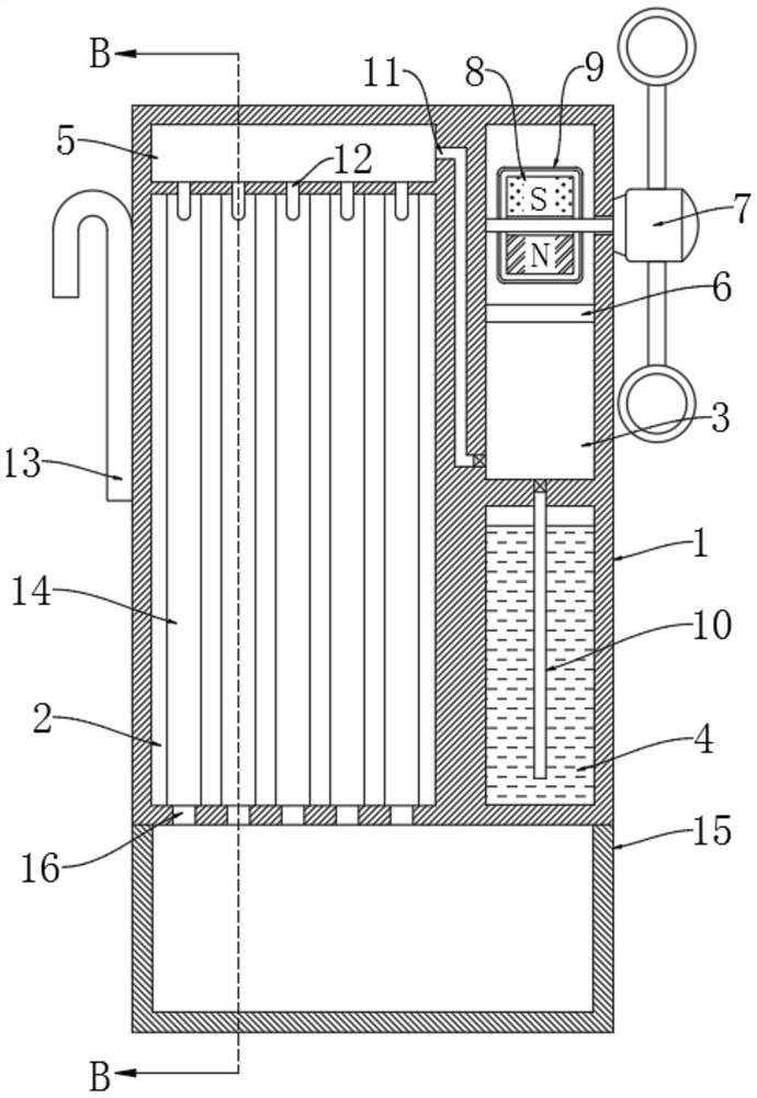
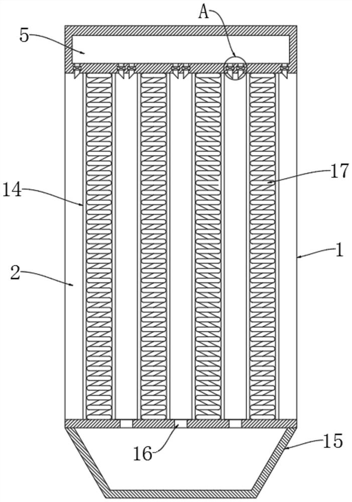
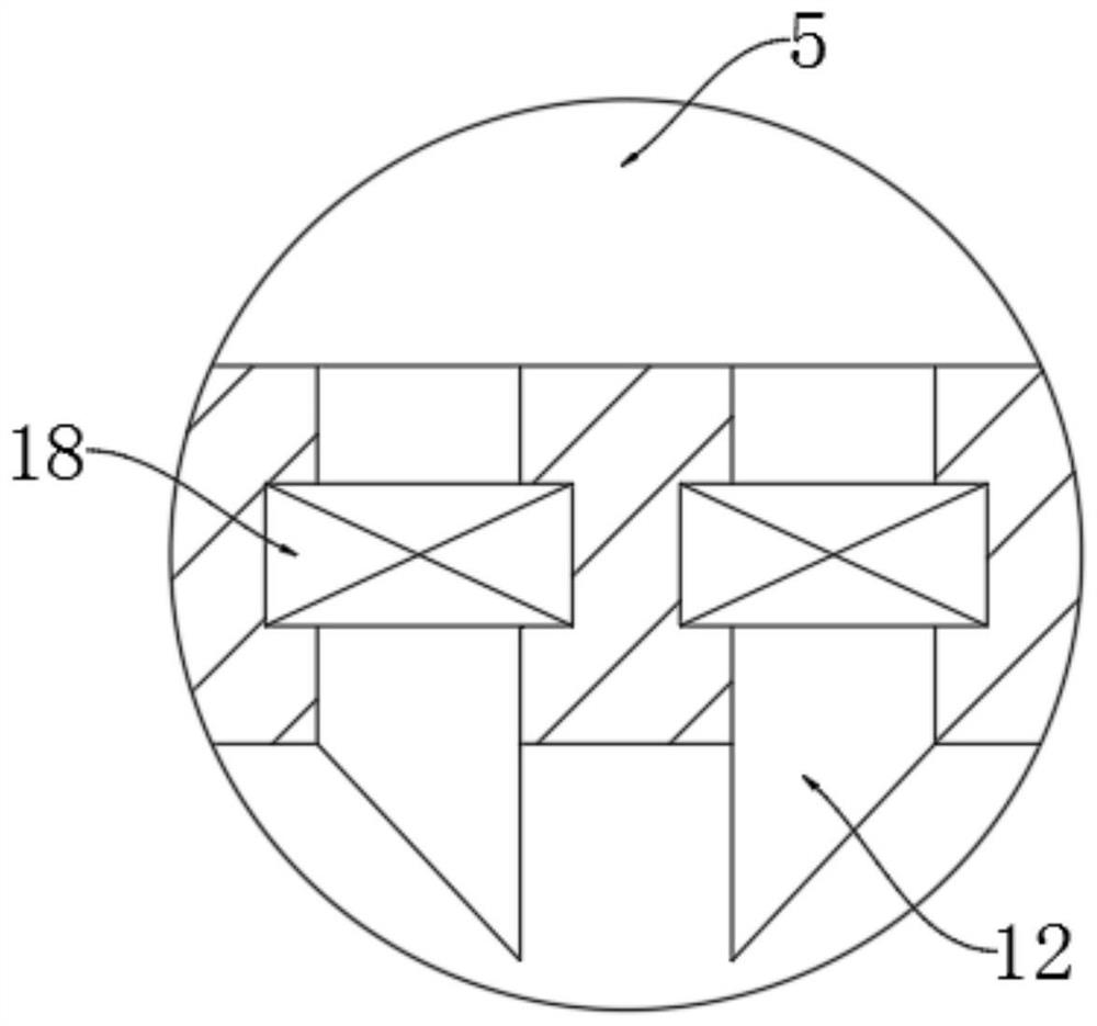
[0023] refer to Figure ...


PUM


Abstract

The invention discloses a using method of an electrostatic dust collection device for a construction site. The method comprises the following steps of: S1, injecting cleaning water, i.e. injecting a certain volume of clear water into a water storage position of the dust collection device; S2, mounting the dust collection device, i.e. fixedly hanging the dust collection device at a high position ofa construction site; S3, removing dust, i.e. taking down the dust collection device hung for a period of time from the high position, and pouring out the dust in the air filtered and collected in thedust collection device; and S4, cleaning the dust collection device, i.e. cleaning a dust collection part of the dust collection device. By arranging dust removal pipes, springs and a driving mechanism, wind power can be used as a driving force to enable the dust removal pipes to generate static electricity to adsorb dust in the air, meanwhile, water can be pumped to clean the surface of the dustremoval pipes, and good dust suction capacity can be guaranteed to the dust removal pipes all the time, therefore the automatic dust removal function of a construction site is achieved.

Description

technical field [0001] The invention relates to the field of construction equipment, in particular to a method for using an electrostatic precipitator for a construction site. Background technique [0002] Due to the characteristics of the construction industry, the air near the construction site will be filled with a lot of dust and other impurities. This is the most common problem in the construction industry. Serious impact, inhalation will cause various respiratory diseases, and once the dust enters the construction machinery, it will shorten the service life of the machine, so in consideration of safety itself, coupled with the current high requirements for environmental protection in the country, construction A lot of dust removal equipment is needed on the construction site to purify the air and remove dust and dust. [0003] However, at present, the traditional dust collector adopts a filter cartridge dust collector. After a period of use of this kind of dust collec...

Claims


Application Information

Patent Timeline
Patent Type & Authority Applications(China)
IPC IPC(8): B03C3/06B03C3/30B03C3/41B03C3/49B03C3/66B03C3/78
CPCB03C3/06B03C3/30B03C3/41B03C3/49B03C3/66B03C3/78
Inventor 毛嘉豪
Owner 山东一滕建设集团有限公司
Why Eureka
Try Eureka