Stone crushing device for exploiting rare earth efficiently

A crushing device and rare earth technology, applied in cleaning methods and utensils, removal of smoke and dust, grain processing, etc., can solve problems such as poor crushing effect of briquette on stones, and achieve rich functions, good dust removal function, and good crushing effect.

Inactive Publication Date: 2020-10-09
吴巧娣
View PDF1 Cites 0 Cited by
  • Summary
  • Abstract
  • Description
  • Claims
  • Application Information

AI Technical Summary

Problems solved by technology

[0005] However, the crushing device crushes the stones through the briquetting block, but the briquetting block will be subjected to the reaction force of the elastic member during the descent process, resulting in poor crushing effect of the briquetting block on the stone block

Method used


Image

  • Stone crushing device for exploiting rare earth efficiently
  • Stone crushing device for exploiting rare earth efficiently
  • Stone crushing device for exploiting rare earth efficiently

Examples


Embodiment 1

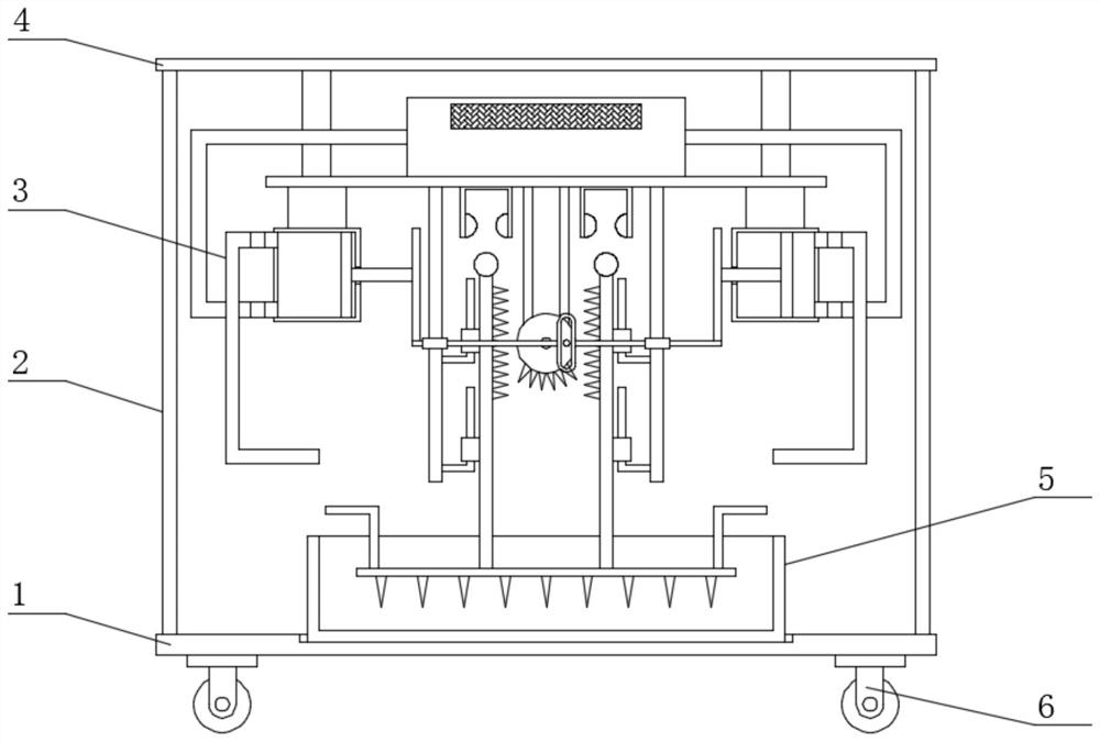
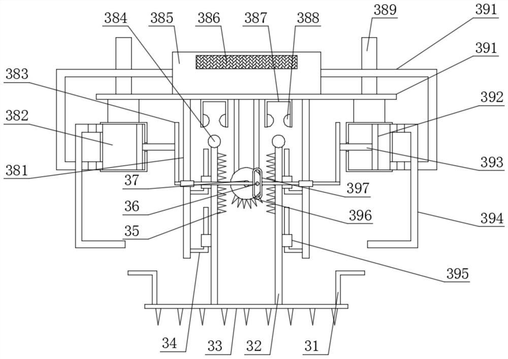
[0024] See Figure 1-Figure 4 , The present invention provides a technical solution: a high-efficiency rare earth stone crushing device, including a first support plate 1, the upper surface of the first support plate 1 is placed with a crushing box 5, the first support plate 1 is provided with The second support plate 4, both ends of the upper surface of the first support plate 1 are welded with side plates 2 corresponding to the second support plate 4, and a crushing mechanism 3 is provided under the second support plate 4. The crushing mechanism 3 includes a third Support plate 391, the connection between the third support plate 391 and the second support plate 4 is welded with a second limit plate 389, a drive motor 37 is welded under the third support plate 391, and drive teeth are welded to the output end of the drive motor 37 Disk 396, a crushing plate 33 is arranged under the drive motor 37, the upper surface of the crushing plate 33 is provided with a first transmission...

Embodiment 2

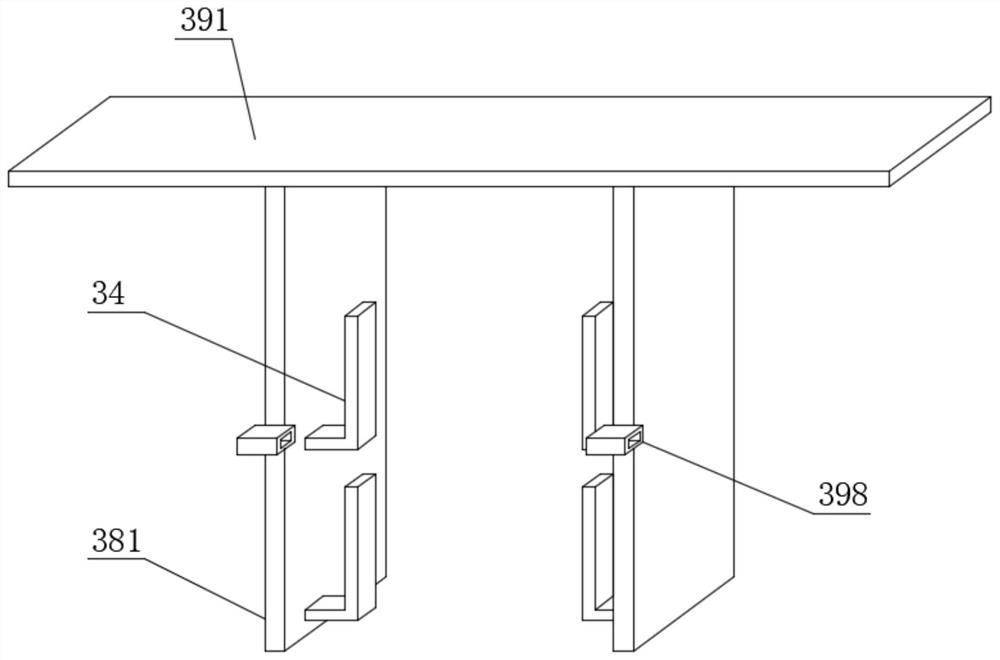
[0030] On the basis of embodiment 1, in order to enrich the functions of the crushing device, in this embodiment, preferably, the lower surface of the third support plate 391 is further welded with a dust removal cylinder 382 at both ends, and the dust removal cylinder 382 is provided with a piston. 392. One end of the dust removal cylinder 382 is slidably connected with a third transmission plate 393 corresponding to the piston 392, a transmission member 397 is provided on one side of the driving motor 37, and a transmission cylinder 36 corresponding to the transmission member 397 is provided on the driving motor 37 , The bottom end of the first limiting plate 381 is welded with a second limiting sleeve 398 slidably connected to the transmission member 397, and the two ends of the transmission member 397 are provided with a second transmission plate 383 corresponding to the third transmission plate 393, One end of the dust removal cylinder 382 is provided with a dust removal ho...


PUM


Abstract

The invention discloses a stone crushing device for exploiting rare earth efficiently and relates to the technical field of rare earth exploiting. The stone crushing device comprises a first support plate. A crushing box is arranged on the upper surface of the first support plate. A second support plate is arranged above the first support plate. The two ends of the upper surface of the first support plate are provided with side plates matched with the second support plate. A crushing mechanism is arranged below the second support plate. The crushing mechanism comprises a third support plate. Asecond limiting plate is arranged at the connection position of the third support plate and the second support plate. A driving motor is arranged below the third support plate. A driving toothed discis arranged at the output end of the driving motor. A crushing plate is arranged below the driving motor. The stone crushing device is simple in structure and convenient to use; when the stone crushing device is used, stone is crushed through impact of the crushing plate; and in addition, the crushing plate is accelerated in the descending process, and thus, the stone crushing effect of the crushing plate can be better.

Description

Technical field [0001] The invention belongs to the technical field of rare earth mining, and specifically relates to a high-efficiency rare earth mining device using stone crushing. Background technique [0002] In rare earth mining, a large number of rocks are produced, which can be used after being broken. However, manually breaking the rocks is not only time-consuming and labor-intensive, but also inefficient. [0003] Chinese Patent (Publication No. CN206622155U) discloses a multiple crushing device for garden stones, which includes a bottom plate, a first sprocket, a disc, a circular slide rail, a pulley, a cam, a second sprocket and a chain, and the bottom plate The left and right sides are respectively provided with a left side panel and a right side panel, the top of the left side panel and the right side panel are provided with a top panel, and a second collection box and a first collection box are provided on the bottom plate. [0004] The utility model has the advantage ...

Claims


Application Information

Patent Timeline
Patent Type & Authority Applications(China)
IPC IPC(8): B02C1/00B02C23/00B02C23/18B08B15/04
CPCB02C1/00B02C23/00B02C23/18B08B15/04
Inventor 吴巧娣
Owner 吴巧娣
Why Eureka
Try Eureka