
Mechanical part cleaning and drying device

A technology for drying devices and mechanical parts, applied in drying, dryers, drying gas arrangement, etc., can solve the problems of increasing the work intensity of operators and low cleaning efficiency of mechanical parts, so as to improve stability and cleaning efficiency Effect

Active Publication Date: 2020-09-08
重庆康铖智汇机械制造有限公司
View PDF5 Cites 3 Cited by
  • Summary
  • Abstract
  • Description
  • Claims
  • Application Information

AI Technical Summary

Problems solved by technology

[0003] The existing cleaning and drying device for mechanical parts does not have high cleaning efficiency for mechanical parts, and after the cleaning is completed, the mechanical parts need to be manually transported to the drying device for drying, which increases the work intensity of the operator

Method used


Image

  • Mechanical part cleaning and drying device
  • Mechanical part cleaning and drying device
  • Mechanical part cleaning and drying device

Examples


Embodiment 1

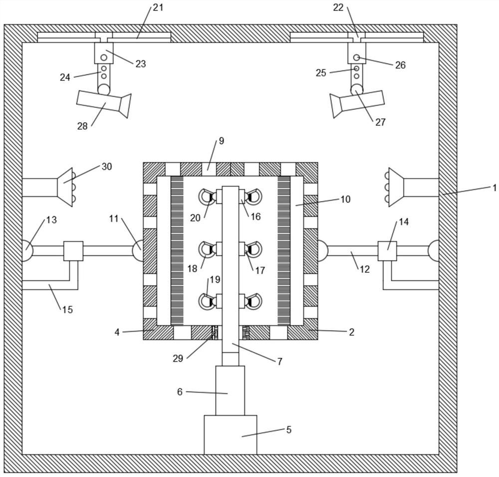
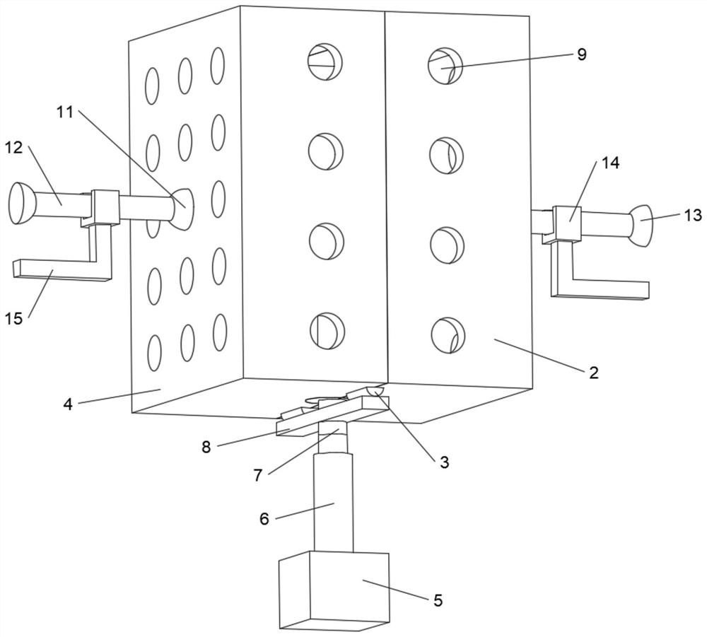
[0020] see Figure 1-3 , in an embodiment of the present invention, a mechanical parts cleaning and drying device includes a box body 1, a right cleaning cylinder 2 is arranged inside the box body 1, a rotating shaft 3 is arranged at the left lower end of the right cleaning cylinder 2, and the rotating shaft 3 is rotatably connected with The left cleaning cylinder 4, the inner bottom surface of the box body 1 is provided with a motor 5, the output end of the motor 5 is fixedly connected with a telescopic rod 6, and the top pipe of the telescopic rod 6 is fixedly connected with a fixed rod 7, and the upper end of the fixed rod 7 extends into the right Cleaning tube 2 and left cleaning tube 4 are provided with a plurality of suspension devices on the inside and on the side wall, and push plate 8 is provided on the side wall of fixed rod 7, and push plate 8 is positioned at rotating shaft 3 just below, and described right cleaning tube 2 and left cleaning The side wall of the cyl...

Embodiment 2

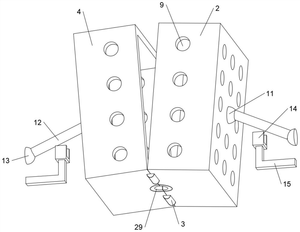
[0027] In order to ensure that the fixed rod 7 can rotate stably and smoothly, this embodiment is further improved on the basis of Embodiment 1. The improvement is: the lower ends of the right cleaning cylinder 2 and the left cleaning cylinder 4 are provided with a shaft sleeve 29, and the shaft sleeve 29 is located outside the fixed rod 7 and the inner diameter of the shaft sleeve 29 is larger than the outer diameter of the fixed rod 7. Through the effect of the shaft sleeve 29, when the right cleaning cylinder 2 and the left cleaning cylinder 4 are separated, the shaft sleeve 29 will not clamp the fixed rod 7 , can make fixed rod 7 rotate smoothly under the drive of motor 5, improve the stability of this device.

[0028]The working principle of this embodiment is: in order to ensure that the fixed rod 7 can rotate stably and smoothly, a shaft sleeve 29 is arranged at the lower ends of the right cleaning cylinder 2 and the left cleaning cylinder 4, and the shaft sleeve 29 is l...


PUM


Abstract

The invention discloses a mechanical part cleaning and drying device. The mechanical part cleaning and drying device comprises a box body, wherein a right washing cylinder is arranged inside the box body, a rotating shaft is arranged at the lower left end of the right washing cylinder, the rotating shaft is rotatably connected with a left cleaning cylinder, the bottom surface of the interior of the box body is provided with a motor, the output end of the motor is fixedly connected with a telescopic rod, the top pipe of the telescopic rod is fixedly connected with a fixing rod, the upper end ofthe fixing rod extends into the right cleaning cylinder and the left cleaning cylinder, a plurality of hanging devices are arranged on the side wall of the fixing rod, a push plate is arranged on theside wall of the fixing rod, through holes which are uniformly distributed are formed in the side wall of the right cleaning cylinder and the side wall of the left cleaning cylinder, a cleaning brushis arranged in each of the right cleaning cylinder and the left cleaning cylinder, and spray heads are arranged on the left side and the right side wall inside the box body. By arranging the motor, the fixing rod can drive the hanging devices to rotate, so that a mechanical part rotates, the part is brushed through the cleaning brushes, and the cleaning efficiency of the mechanical part is improved.

Description

technical field [0001] The invention relates to the field of machinery, in particular to a cleaning and drying device for mechanical parts. Background technique [0002] Mechanical parts, also known as mechanical components, are the basic components of machinery, and they are inseparable individual parts that make up machinery and machines. Mechanical parts are not only a subject of research and design of mechanical basic parts in various equipment, but also a general term for parts and components; after use, there will be a lot of oil on the surface of mechanical parts, and it is necessary to clean the mechanical parts in time, so as to facilitate The mechanical parts continue to be used, and at the same time, a certain amount of water will remain on the surface of the mechanical parts after cleaning, which needs to be dried in time. [0003] The existing cleaning and drying device for mechanical parts does not have high cleaning efficiency for the mechanical parts, and af...

Claims


Application Information

Patent Timeline
IPC IPC(8): B08B3/02B08B1/00B08B1/02B08B13/00F26B21/00F26B25/18
CPCB08B3/022B08B13/00F26B21/004F26B25/185B08B1/20B08B1/12
Inventor 介宝山段碧波
Owner 重庆康铖智汇机械制造有限公司
Features
  • Generate Ideas
  • Intellectual Property
  • Life Sciences
  • Materials
  • Tech Scout
  • Unparalleled Data Quality
  • Higher Quality Content
  • 60% Fewer Hallucinations
Learn More