
A kind of LED module assembly jig and LED module assembly method
A technology of LED modules and fixtures, which is applied in the direction of assembly machines, manufacturing tools, workpiece clamping devices, etc., and can solve the problems of cumbersome assembly, low assembly efficiency, and high labor costs
- Summary
- Abstract
- Description
- Claims
- Application Information
AI Technical Summary
Problems solved by technology
Method used
Image

Examples
Embodiment 1
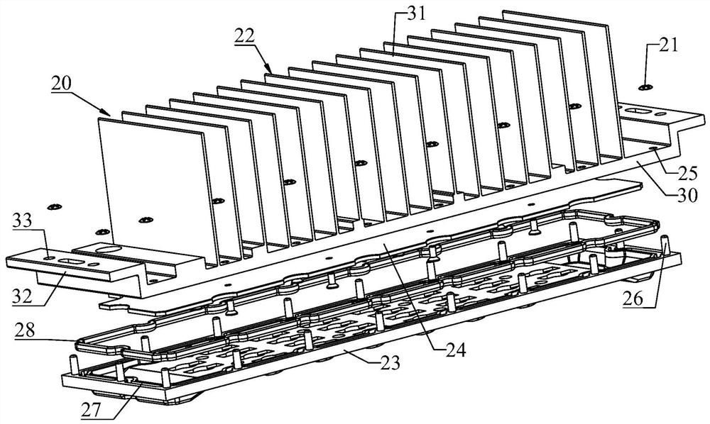
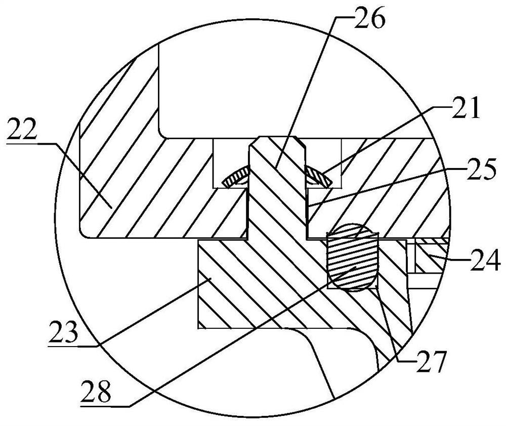
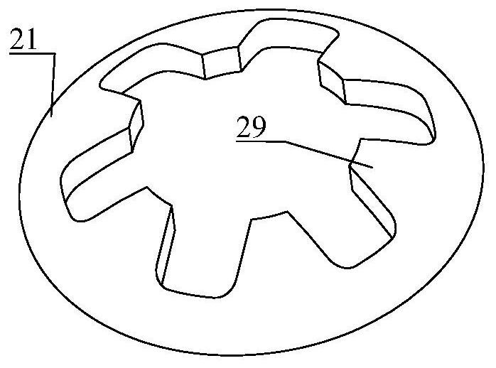
[0039] Please refer to Figure 1 to Figure 4 as well as Figure 9 to Figure 12 , Embodiment 1 of the present invention is: an LED module assembly jig for assembling the LED module 20, such as Figure 1 to Figure 3 As shown, the LED module 20 includes a retaining spring 21, a mounting part 22 and an optical lens 23. The mounting part 22 is used to install the LED lamp panel assembly 24 and the optical lens 23. The assembled LED lamp panel assembly 24 is located on the mounting part. 22 and the optical lens 23 surrounded by the chamber, the mount 22 is provided with a through hole 25, the optical lens 23 is provided with a mounting column 26 that passes through the through hole 25, and the end of the mounting column 26 away from the optical lens 23 passes through the through hole After 25 minutes, it is buckled with the anti-retraction spring 21, thereby realizing the buckle-type fast connection between the mounting part 22 and the optical lens 23. At this time, the anti-retrac...
Embodiment 2
[0053] Please refer to Figure 4 to Figure 12 , an LED module assembly method, comprising the steps of:
[0054] The anti-retraction spring is placed in the placement slot of the lifting device;
[0055] The mounting part is placed in the accommodating structure of the lifting device, and the optical lens is pre-assembled on the mounting part;
[0056] The lifting device further includes a thimble, and the thimble can move relative to the mounting part, so that the back-stop spring is buckled with the mounting post on the optical lens, and the back-stop spring is abutted against the mounting part.
[0057] Further, when placing the anti-retraction circlip, place the anti-retraction circlip in the placing groove through the automatic suction nozzle.
[0058] Since the lifting device used in this embodiment is the LED module assembly jig in Embodiment 1, the LED module assembly method of this embodiment can be described in detail as follows:
[0059] Such as Figure 5 As sho...
PUM
 Abstract
Description
Claims
Application Information