Forced lubrication bearing with distributed holes

A forced lubrication and distributed technology, applied in sliding contact bearings, engine lubrication, bearing components, etc., can solve the problems of large bearing friction coefficient and bearing wear, and achieve good results

Active Publication Date: 2020-09-08
HARBIN ENG UNIV
View PDF7 Cites 0 Cited by
  • Summary
  • Abstract
  • Description
  • Claims
  • Application Information

AI Technical Summary

Problems solved by technology

However, when the equipment is turned on and is under relatively high load and low speed conditions, such as the low-speed navigation stage of the ship, especially the start-up stage of the ship shafting, the shaft and the bearing are in partial contact or even direct contact, and the bearing is in a state of mixed lubrication or boundary lubrication. At this time, the friction coefficient of the bearing is very large. If the bearing load is relatively high in this case, the bearing will be severely worn. This is a problem that equipment users try to avoid and cannot avoid.

Method used


Image

  • Forced lubrication bearing with distributed holes
  • Forced lubrication bearing with distributed holes
  • Forced lubrication bearing with distributed holes

Examples


Embodiment Construction

[0031] The present invention will be described in more detail below with examples in conjunction with the accompanying drawings.

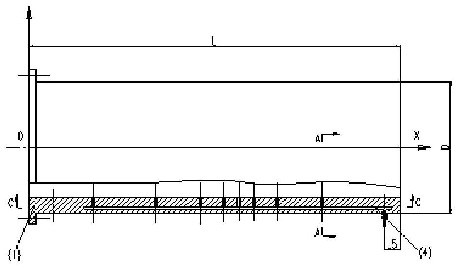
[0032] Radial sliding bearings in low-speed and heavy-load environments are mainly composed of the following two parts: the bearing body and the pressure servo mechanism, and the two parts are connected by pipelines. The bearing can be used for both water lubrication and oil lubrication. The pressurized hole diameter on the bearing can be selected according to the inner diameter of the shaft hole. According to the operating conditions of the shaft system, a reasonable initial pressure of the pressure servo mechanism can be set to realize the forced lubrication of the bearing.

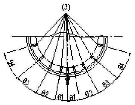
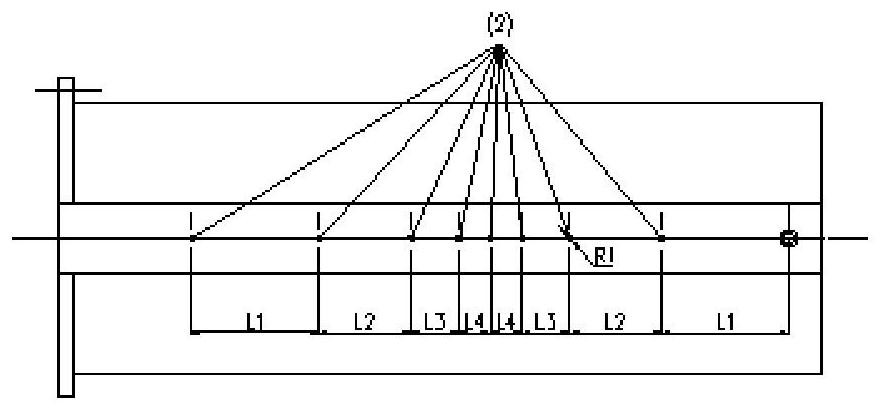
[0033] to combine Figure 1a to Figure 1c , Figure 2a to Figure 2c and image 3 , The bearing body 1 has a pressure hole 2 along the axial direction, a pressure hole 3 along the circumferential direction, and a main pipe 4 inside the bearing body. The wear area between t...


PUM


Abstract

The invention provides a forced lubrication bearing with distributed holes. A header pipe is arranged in a bearing body, pressurization holes leading to the inner surface of the bearing body are axially and circumferentially formed in the bearing body, all the pressurization holes are gathered in the header pipe in the bearing body, the header pipe is connected with a pressure servo mechanism through a pipeline, if the bearing body is circumferentially spread, the pressurization holes form an M*N grid, the distances between the pressurization holes are not uniformly distributed in axial and circumferential directions, and the distances between the pressurization holes close to the maximum pressure point are decreased gradually. The pressure servo mechanism is started when detecting that ashaft system is under a low-speed operation condition, a pressurization medium is forcedly injected below the operating shaft system through the pressurization holes, so that the pressurization mediumsprayed out of the pressurization holes lifts a position with larger shaft system load, the shaft system is ensured to always form a liquid film with the bearing under the rotation condition, the poor lubrication state of the bearing is improved, and the frictional wear of the bearing is relieved.

Description

technical field [0001] The application of the present invention relates to a radial sliding bearing, specifically a radial sliding bearing with forced lubrication. Background technique [0002] Due to the advantages of large bearing capacity and good adaptability, radial sliding bearings have been widely used in rotating components of ships and machinery. For the above application fields, controlling operating costs and increasing bearing service life are the primary conditions for selecting bearings , so reducing the friction and wear of the bearing system is an important indicator that is given priority in bearing design. Under the rated operating conditions of the shaft system, the shaft and the bearing are separated by a layer of liquid film. Due to the shearing effect of the liquid film, the friction coefficient is not large, and the shaft and bearing operating in the hydrodynamic lubrication stage have very little wear. Almost negligible. However, when the equipment ...

Claims


Application Information

Patent Timeline
Patent Type & Authority Applications(China)
IPC IPC(8): F16C25/04F16C33/04F16N7/38
CPCF16C25/04F16C33/04F16N7/38F16N2210/14
Inventor 曹贻鹏张润泽张新玉张文平刘晨杨国栋明平剑柳贡民国杰赵晓臣
Owner HARBIN ENG UNIV
Why Eureka
Try Eureka