
Full-automatic magnetic ring inductor winding machine capable of winding long wire

A magnetic ring inductance and winding machine technology, applied in the manufacture of inductors/transformers/magnets, circuits, coils, etc., can solve the problems of reducing processing speed, reducing processing accuracy, elongation, etc., and achieve the effect of reducing damage

Pending Publication Date: 2020-09-08
黄日元
View PDF1 Cites 4 Cited by
  • Summary
  • Abstract
  • Description
  • Claims
  • Application Information

AI Technical Summary

Problems solved by technology

[0005] Aiming at the deficiencies of the existing technology, the present invention provides a fully automatic magnetic ring inductance winding machine that can wind long wires, which solves the problem of deformation of copper wires due to heat generation, which may even lead to elongation or even breakage in serious cases, resulting in waste products during processing, reducing the Processing accuracy, and need to stop to process the magnetic ring, which greatly reduces the problem of processing speed

Method used


Image

  • Full-automatic magnetic ring inductor winding machine capable of winding long wire
  • Full-automatic magnetic ring inductor winding machine capable of winding long wire
  • Full-automatic magnetic ring inductor winding machine capable of winding long wire

Examples


Embodiment Construction

[0036] The following will clearly and completely describe the technical solutions in the embodiments of the present invention with reference to the accompanying drawings in the embodiments of the present invention. Obviously, the described embodiments are only some, not all, embodiments of the present invention. Based on the embodiments of the present invention, all other embodiments obtained by persons of ordinary skill in the art without making creative efforts belong to the protection scope of the present invention.

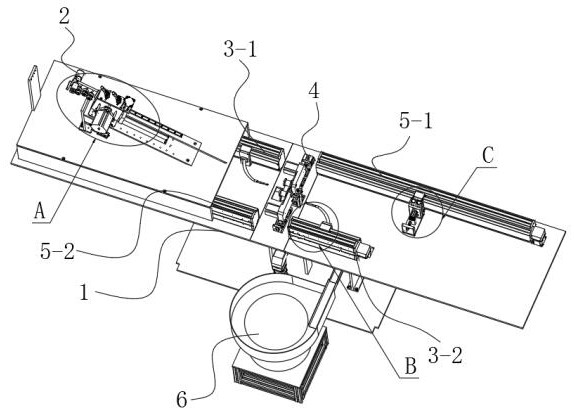
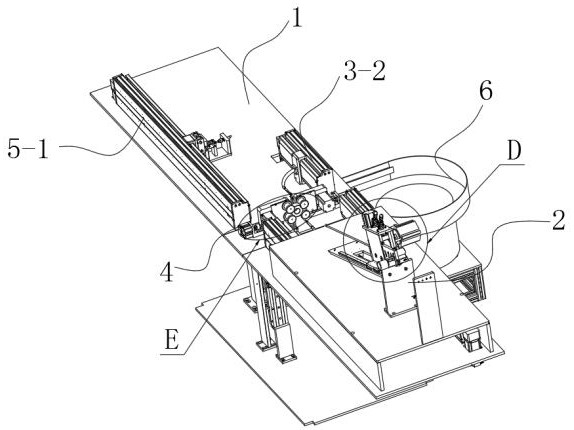
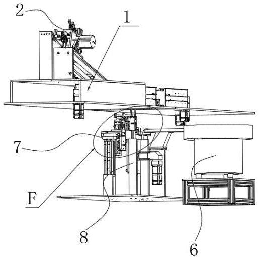
[0037] see Figure 1-12 , the embodiment of the present invention provides a technical solution: a fully automatic magnetic ring inductance winding machine that can wind long wires, including a winding machine body 1, and the surface of the winding machine body 1 is respectively fixedly connected with a first wire hooking mechanism 3 -1, the second hooking mechanism 3-2, the magnetic ring clamping mechanism 4, the first range extending mechanism 5-1 and the se...


PUM


Abstract

The invention discloses a full-automatic magnetic ring inductor winding machine capable of winding a long wire. The full-automatic magnetic ring inductor winding machine comprises a winding machine body, wherein the surface of the winding machine body is fixedly connected with a first wire hooking mechanism, a second wire hooking mechanism, a magnetic ring clamping mechanism, a first range extending mechanism and a second range extending mechanism, and the first wire hooking mechanism, the second wire hooking mechanism, the first range extending mechanism and the second range extending mechanism are symmetrically distributed along the center line. The invention belongs to the technical field of automatic winding processing of magnetic ring inductors. According to the invention, a horizontal structure is adopted, so that a mode that a copper wire is hooked from the middle starting point can be realized, and wire hooking can be performed from left side and right side; and the copper wireis doubled in length through the range extending and wire hooking mechanism, the range extending and wire hooking mechanism uses a roller structure to hook the wire, and a sliding friction mode whena crochet hook is used for hooking the wire is changed into a rolling friction mode, so that the damage to an enameled insulating layer of an enameled copper wire is greatly reduced so as to achieve the full-automatic wire hooking of a long magnetic ring inductor wire.

Description

technical field [0001] The invention relates to the technical field of automatic winding processing, in particular to a fully automatic magnetic ring inductance winding machine capable of winding long wires. Background technique [0002] Common-mode inductors, also known as common-mode choke coils, are often used to filter common-mode electromagnetic interference signals in computer switching power supplies. In board design, common-mode inductors also function as EMI filters to suppress high-speed signal lines. The electromagnetic waves radiate outward, the filter circuit of the common mode inductor, La and Lb are the common mode inductor coils, these two coils are wound on the same iron core, the number of turns and the phase are the same, so when the normal current in the circuit flows When passing through a common-mode inductor, the current generates a reverse magnetic field in the inductance coil wound in the same phase to cancel each other out. At this time, the normal ...

Claims


Application Information

Patent Timeline
Patent Type & Authority Applications(China)
IPC IPC(8): H01F41/08H01F41/082H01F41/096
CPCH01F41/08H01F41/082H01F41/096
Inventor 黄日元
Owner 黄日元
Learn More