Stuffing sand removing method for casting start of continuous casting steel ladle

A technology for draining sand and continuous casting steel, applied in the field of continuous casting in the metallurgical industry, can solve the problems of difficult layout, easy freezing of molten steel, increase of fault points, etc., and achieve a good effect of elimination.

Inactive Publication Date: 2020-09-11
CONTINUOUS CASTING TECH ENG OF CHINA
View PDF11 Cites 5 Cited by
  • Summary
  • Abstract
  • Description
  • Claims
  • Application Information

AI Technical Summary

Problems solved by technology

[0004] The invention patent "A Method for Controlling Drainage Sand Entering the Tundish in Continuous Casting Process" (application number 201810564363.6) adopts the method of pausing during the rotation of the continuous casting ladle from the molten steel receiving position to the pouring position, opening the ladle sliding nozzle, removing the drainage sand, and then Close the sliding nozzle, then rotate the ladle to the pouring position, open the sliding nozzle for normal pouring, and blow inert gas into the ladle through the venting block of the ladle nozzle before the ladle rotates from the receiving position until it reaches the pouring position. To increase the temperature of the molten steel in the nozzle area of ​​the ladle, prevent the condensation of molten steel in the upper nozzle of the ladle, and affect the success rate of pouring after the sliding nozzle is opened
The disadvantage of this patent is that it is necessary to stop during the rotation of the ladle to remove the drainage sand, which not only prolongs the preparation time for continuous casting molten steel, but also starts the sliding nozzle of the ladle twice, and the molten steel in the ladle upper nozzle area is easy to freeze; Nozzle breathable bricks and air blowing operation increase the failure points in the preparation process of continuous casting ladle opening and pouring
The disadvantages of this patent are: operating the ladle sliding nozzle twice, which increases the operation steps and time of ladle pouring, and the molten steel in the upper nozzle area of ​​the ladle is easy to freeze; the sliding nozzle mechanism is equipped with a vent plug, the structure is complicated, and the failure rate increases
The disadvantages of this patent are similar to those of patent 201510526147.9, and the recovery device is installed in the limited space at the bottom of the ladle, which is difficult to arrange, review loading and unloading, and has limited capacity, making it difficult to implement and achieve good results

Method used


Image

  • Stuffing sand removing method for casting start of continuous casting steel ladle
  • Stuffing sand removing method for casting start of continuous casting steel ladle
  • Stuffing sand removing method for casting start of continuous casting steel ladle

Examples


Embodiment Construction

[0025] The present invention will be further described below in conjunction with the accompanying drawings and embodiments.

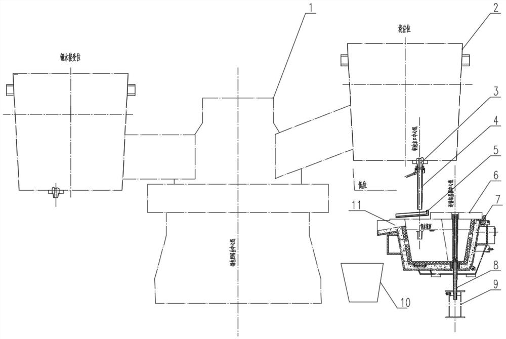
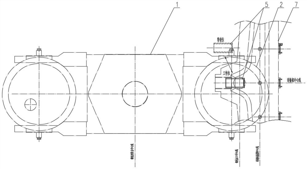
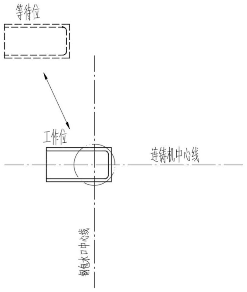
[0026] Such as Figure 1 to Figure 3 As shown, in the continuous casting process of a continuous casting machine, a ladle of molten steel needs to be replaced after the pouring of the next ladle of molten steel. The replacement of the continuous casting ladle 2 is usually realized through the ladle turret 1, which can rotate 360°. The ladle turret 1 is provided with two slewing arms that can be raised and lowered for receiving the continuous casting ladle 2 . At the end of the pouring of the last ladle of molten steel, the next ladle of molten steel to be replaced is hoisted to the rotary arm at the receiving position of molten steel, and the preparations for the sliding nozzle 3 of the ladle are completed (such as installation of oil cylinders, gas pipelines, etc.), continuous casting The acceptance of ladle 2 can be carried out when the rotary arm is...


PUM

PropertyMeasurementUnit
thicknessaaaaaaaaaa
heightaaaaaaaaaa
widthaaaaaaaaaa

Abstract

The invention discloses a stuffing sand removing method for casting start of a continuous casting steel ladle. A movable flow guiding chute is arranged in a space between the lower side of a protective sleeve rising to a high position and the upper edge of an intermediate tank; the continuous casting steel ladle rises to a high position and directly rotates to a casting station from a molten steelreceiving station, after casting is prepared well and the protective sleeve is installed, the flow guiding chute moves to a work station under the protective sleeve, a sliding nozzle is opened, and stuffing sand flows into the flow guiding chute and is guided into an overflowing opening on the intermediate tank or directly guided into an overflowing tank outside the intermediate tank; after all the stuffing sand is guided away and the molten steel flows out, the flow guiding chute is moved to the waiting station, where the flow guiding chute does not influence hoisting of the intermediate tank, outside the intermediate tank, the molten steel flows into the intermediate tank, the continuous casting steel ladle descends to a low position, the protective sleeve dips into the molten steel inthe intermediate tank, and casting start is completed. The stuffing sand removing method for casting start of the continuous casting steel ladle does not need stop, does not influence the existing steel ladle casting start preparation procedure and does not prolong the overall casting start time, and a good removing effect is achieved.

Description

technical field [0001] The invention belongs to the technical field of continuous casting in the metallurgical industry, and in particular relates to a method for removing drainage sand when a continuous casting ladle is poured. Background technique [0002] When the molten steel in the continuous casting ladle is poured, the drainage sand filled in the ladle nozzle will flow out first. If no measures are taken, the drainage sand flowing out each time the pouring is started or the oxygen-burning products produced during the oxygen-burning start-up will be Enter the continuous casting tundish and become impurities in the tundish steel water. If the impurities in the tundish liquid steel cannot float up and flow out from the overflow in time, they will enter the continuous casting billet and form large non-metallic inclusions or surface in the billet. Slag inclusions reduce the quality of continuous casting slabs and severely restrict the continuous casting production of high-...

Claims


Application Information

Patent Timeline
Patent Type & Authority Applications(China)
IPC IPC(8): B22D11/10B22D11/11
CPCB22D11/10B22D11/11
Inventor 周干水韩占光张斌
Owner CONTINUOUS CASTING TECH ENG OF CHINA
Why Eureka
Try Eureka