
camera device

A technology of a camera device and a camera part is applied in the field of noise devices to achieve the effect of reducing noise

Active Publication Date: 2018-08-28
KOKUSA ELECTRIC CO LTD
View PDF5 Cites 0 Cited by
  • Summary
  • Abstract
  • Description
  • Claims
  • Application Information

AI Technical Summary

Problems solved by technology

[0007] According to the existing general method, which is simple averaging for the optical black (OB) area and the same pixels, there will be the following problems, that is, pixels based on defects such as white scars, pixels with excitation by radiation or flickering behavior, etc. Values ​​that should not be included in the averaging are also averaged together

Method used


Image

  • camera device
  • camera device
  • camera device

Examples


Embodiment Construction

[0032] One embodiment of the present invention will be described below using the drawings.

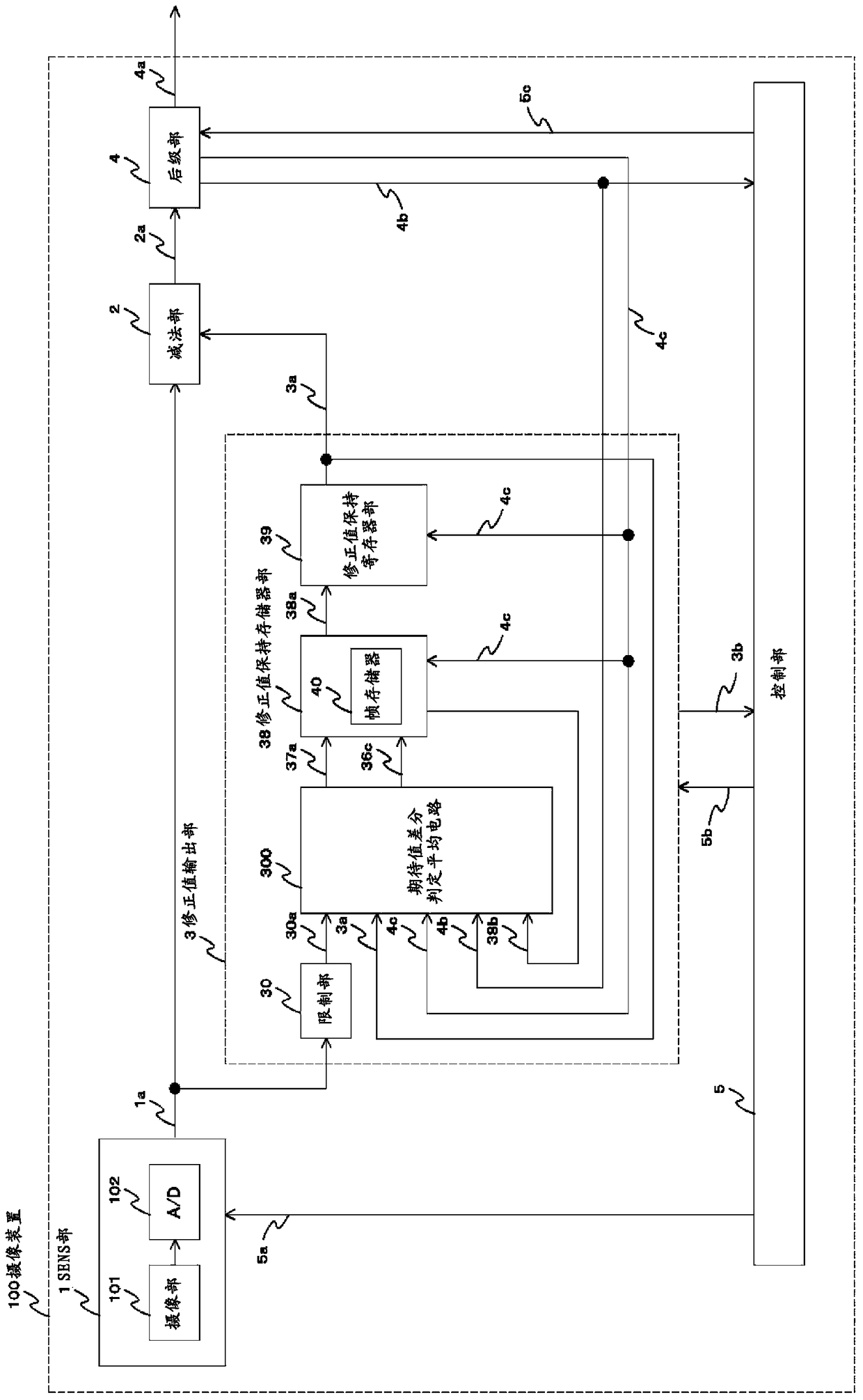
[0033] figure 1 It is a block diagram for explaining an imaging device as an embodiment of the present invention.

[0034] figure 1 Among them, the imaging device 100 is composed of a SENS unit 1 , a subtraction unit 2 , a correction value output unit 3 , a post-stage unit 4 , and a control unit 5 .

[0035] The SENS unit 1 is composed of an imaging unit 101 having an imaging element as an imaging unit, and an A / D conversion unit (Analog-to-Digital converter) 102. The light is converted into an electrical signal, and a digital output signal 1 a is output through a series of operation units until the A / D conversion unit converts the electrical signal into a digital signal that can be processed by a logic circuit. The SENS unit 1 is controlled by a control signal 5 a output from the control unit 5 .

[0036] The subtraction unit 2 receives the digital output signal 1a from the SENS u...


PUM


Abstract

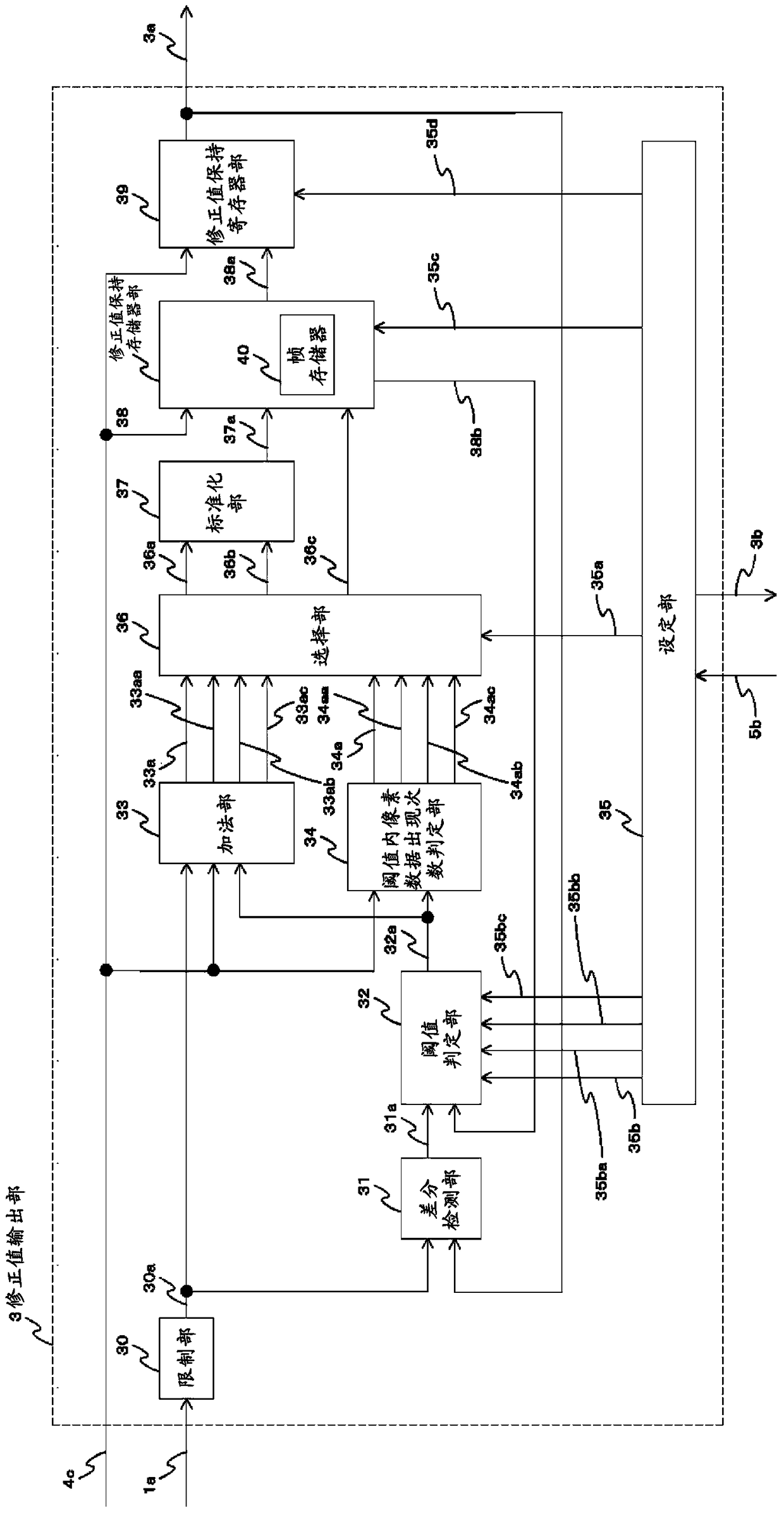
The object of the present invention is to realize an extreme value exclusion average circuit for environment tracking by using small-scale logic by performing an operation of shifting to an appropriate threshold value without sorting the data while excluding extreme values ​​that should be excluded from the average. . The imaging device of the present invention includes: an imaging unit, a correction value output unit, and a subtraction unit, and the imaging device is characterized in that the correction value output unit judges the signal level of each pixel output from the light-shielded pixel area of ​​the imaging unit by using a plurality of thresholds. And select pixel signals with signal levels within a predetermined range, average the selected pixel signals, and output the averaged signal as a correction value signal, and the subtraction unit subtracts the correction value signal from the photosensitive pixel of the above-mentioned imaging unit. The signal output by the zone.

Description

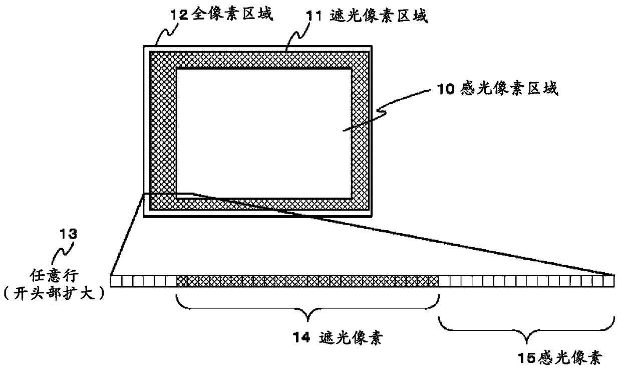
technical field [0001] The present invention relates to an imaging device, and more particularly to an apparatus for reducing noise contained in an image signal output from an imaging element. Background technique [0002] There is a small output difference between each pixel of the imaging element, which is known as fixed pattern noise. It is also known that among a plurality of pixels, there are defective pixels, and there are pixels that always show outstanding output as pixel defects. In addition, in order to set the output at the time of shading to 0 output, an optical black pixel (light shading) as a reference is generally used, and the optical black pixel is subtracted from the video pixel offset on the circuit side of the imaging device. [0003] At present, after correcting the dark current unevenness in the vertical direction of the screen obtained from the signals of the vertical shading pixels of the 4 lines first read from the effective pixels on the light-rece...

Claims


Application Information

Patent Timeline
Patent Type & Authority Patents(China)
IPC IPC(8): H04N5/357H01L27/146H04N5/361H04N5/365
CPCH01L27/14623H04N25/67H04N25/63H04N25/745
Inventor 小坂大树池田志郎宇佐美裕丈梶村佳弘
Owner KOKUSA ELECTRIC CO LTD
Learn More