Waxing device for textile processing

A technology of textile thread and wax roller, applied in the field of textile processing, can solve the problems of waste and low utilization rate of wax blocks, and achieve the effect of avoiding waste and saving resources.

Inactive Publication Date: 2020-09-11
李海燕
View PDF1 Cites 3 Cited by
  • Summary
  • Abstract
  • Description
  • Claims
  • Application Information

AI Technical Summary

Problems solved by technology

A kind of waxing device for textile processing in the above-mentioned patent has the following disadvantages: although the wax block can be effectively contacted with the textile thread to achieve uniform waxing, the utilization rat

Method used


Image

  • Waxing device for textile processing
  • Waxing device for textile processing
  • Waxing device for textile processing

Examples


Example Embodiment

[0033] Example 1

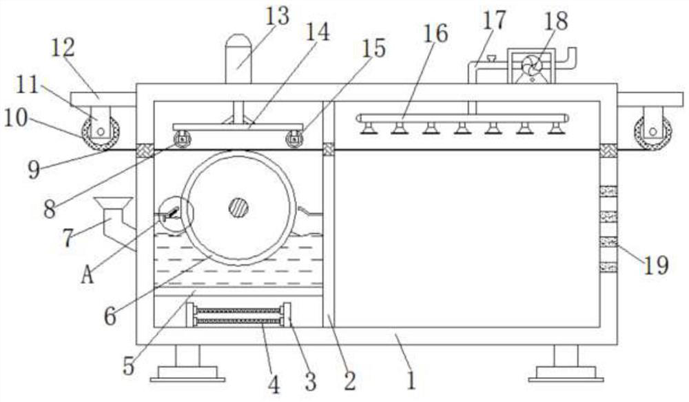
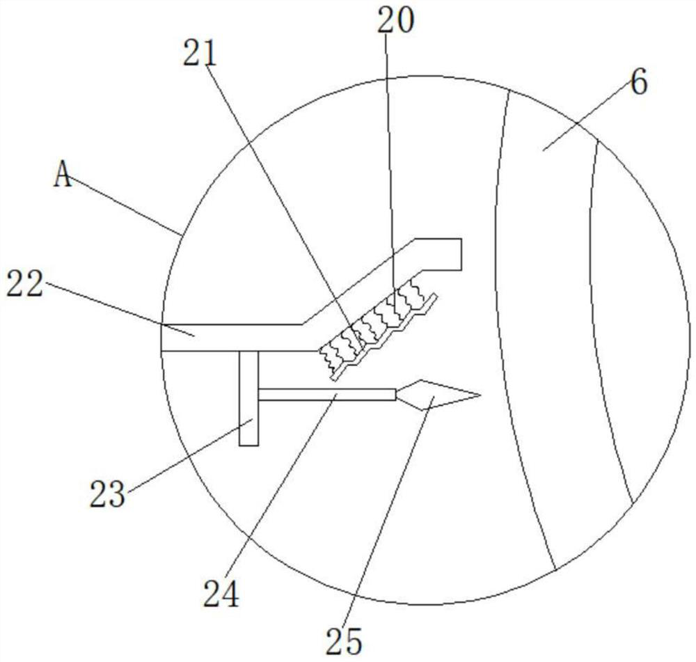
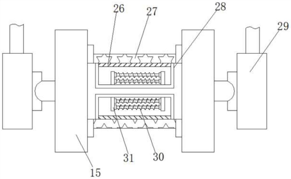
[0034] refer to Figure 1-5 , a waxing device for textile processing, comprising a box body 1, a feed hopper 7 is plugged into one side of the box body 1, and a first connecting plate 5 is welded on one side of the box body 1 inner wall, and the box body 1 The inner wall of the bottom is connected with the first mounting plate 3 by bolts, and the first resistance wire 4 is connected to the outer wall of one side of the first mounting plate 3 by bolts, and the outer wall of one side of the box body 1 is connected with the protective shell 32 by bolts, and the protective shell One side inner wall of 32 is connected with a motor by bolts, and one end of the output shaft of the motor is provided with a waxing roller 6, and the waxing roller 6 is located inside the box body 1, and one side outer wall of the box body 1 is connected with a second fixing plate 12 by bolts , and the bottom outer wall of the second fixed plate 12 is connected with the first fixed pla...

Example Embodiment

[0044] Example 2

[0045] refer to Image 6 , a waxing device for textile processing. Compared with Embodiment 1, the inner walls of both sides of the box body 1 are rotatably connected with transmission rollers 33, and the textile thread 9 and the transmission roller 33 form a transmission connection.

[0046] Working principle: when waxing the textile thread, people can first add the wax block to the bottom of the box body 1 through the feed hopper 7, and the wax block added to the bottom of the box body 1 can be heated by the first resistance wire 4 to form wax oil Then people start the motor, and the motor drives the waxing roller 6 to rotate, and the wax oil at the bottom of the casing 1 can be adhered to its surface when the waxing roller 6 rotates, and then the textile thread 9 contacts with the waxing roller 6, which can Completing the waxing work on the textile thread 9 saves resources more than traditional wax block waxing, and avoids the waste of a large number of ...


PUM


Abstract

The invention discloses a waxing device for textile processing. The waxing device comprises a box; a feeding hopper is connected to the outer wall of one side of the box in an inserted mode, and a first connecting plate is arranged on the inner wall of one side of the box; a first mounting plate is arranged on the inner wall of the bottom of the box, and a first resistance wire is arranged on theouter wall of one side of the first mounting plate; a protective shell is arranged on the outer wall of one side of the box, and a motor is arranged on the inner wall of one side of the protective shell; a waxing roller is arranged at one end of an output shaft of the motor and located in the box; a second fixing plate is arranged on the outer wall of one side of the box, and a first fixing plateis arranged on the outer wall of the bottom of the second fixing plate; and the outer wall of one side of the first fixing plate is rotationally connected with an unwinding roller, and a textile thread is wound on the circumferential outer wall of the unwinding roller. Compared with traditional waxing by wax blocks, more resources are saved, and waste generated by the inability of the large numberof wax blocks to make contact with the textile thread is avoided.

Description

technical field [0001] The invention relates to the technical field of textile processing, in particular to a waxing device for textile processing. Background technique [0002] With the popularization of textiles, during the weaving process of textiles, the friction between threads generates static electricity. In order to reduce the friction between textile threads, the textile threads are waxed, but manual waxing takes a long time. And the uniformity is poor, so it is necessary for the waxing device on the textile line. [0003] After retrieval, the Chinese Patent Publication No. is CN107963520A, which discloses a waxing device for textile processing, including a main body box, and the top and bottom of the left side of the main body box are respectively fixedly connected with a first horizontal plate and a second horizontal plate , the top and bottom of one side of the inner wall of the main body box are fixedly connected with support rods, the bottom of the inner wall ...

Claims


Application Information

Patent Timeline
IPC IPC(8): B65H71/00
CPCB65H71/007B65H2701/31
Inventor 李海燕
Owner 李海燕
Why Eureka
Try Eureka