Dust removing equipment for mine and use method thereof

A technology for dust removal equipment and mines, applied in mining equipment, mechanical equipment, dust prevention, etc., can solve problems such as increase, inability to adapt to dust removal, fixed absorption range of gas collection pipe, etc., and achieve the effect of improving the range

Active Publication Date: 2020-09-11
惠东嘉华材料有限公司
View PDF13 Cites 2 Cited by
  • Summary
  • Abstract
  • Description
  • Claims
  • Application Information

AI Technical Summary

Problems solved by technology

The invention is novel in design, uses multi-stage fans to increase the pressure difference between the gas in the dust removal device and the outside air, accelerates the gas flow rate, thereby increasing the dust removal capacity, and uses the wind guide fins to guide the dust to enter the pipe body in a spiral shape, and the air flow Rotational movement is obtained, so that the dust entering the pipe body forms a vortex, which increases the dust collection range and speed, and improves the dust removal effect", but there are still defects, the absorption range of the gas collection pipe is fixed, and it cannot adapt to different ranges of dust removal

Method used


Image

  • Dust removing equipment for mine and use method thereof
  • Dust removing equipment for mine and use method thereof
  • Dust removing equipment for mine and use method thereof

Examples


Embodiment 1

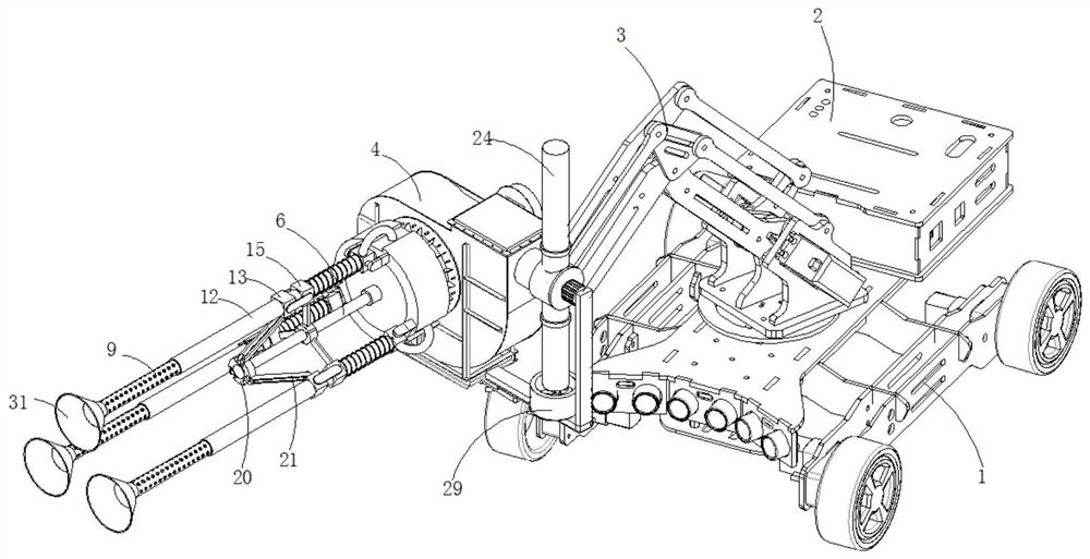
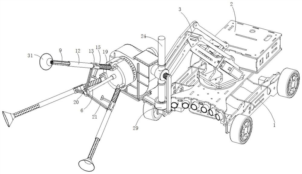
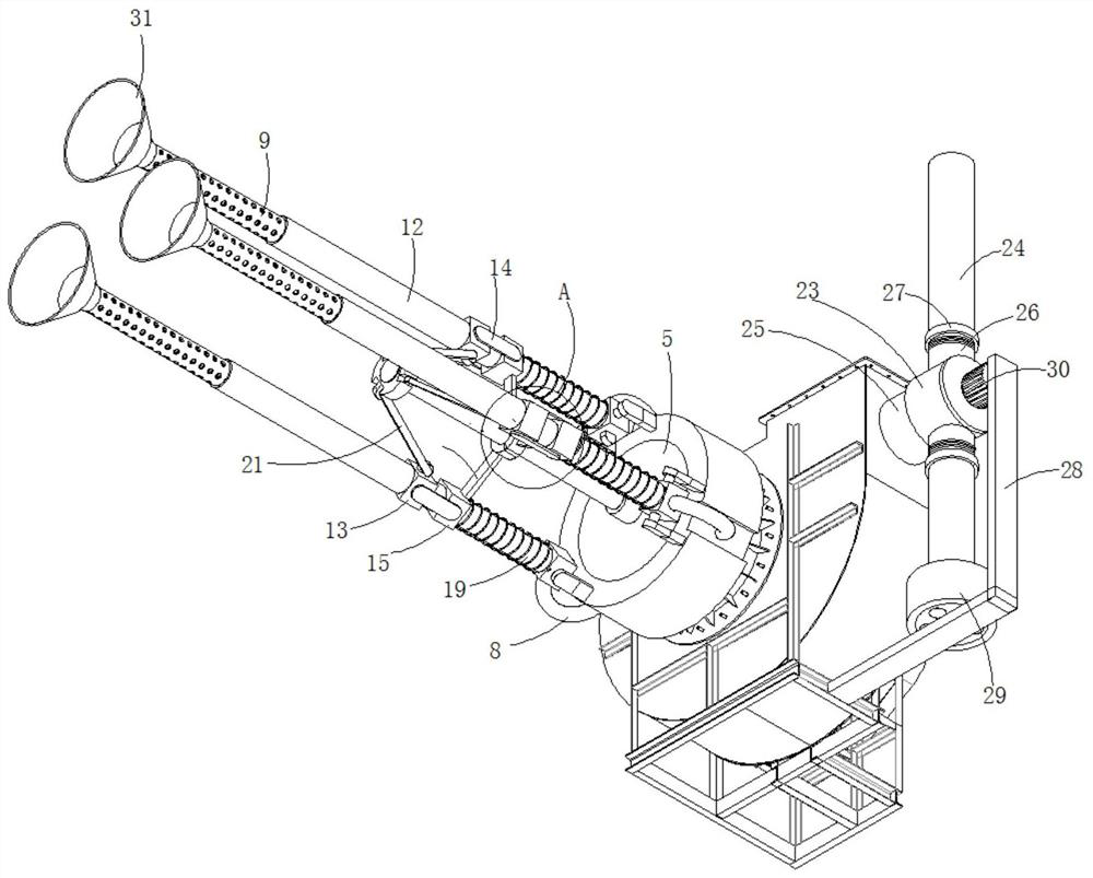
[0038] refer to Figure 1-6 , a kind of dust removal equipment for mines, including car body 1, PLC electric control box 2 and mechanical arm 3, PLC electric control box 2 and mechanical arm 3 are installed on the car body 1, and the moving end of mechanical arm 3 is fixed through a bracket There is a centrifugal fan 4, the air inlet of the centrifugal fan 4 is fixedly connected with a sealing plate 5, the middle part of the sealing plate 5 is equipped with a telescopic cylinder 6, and the edge of the sealing plate 5 is movably connected with an evenly distributed air cylinder 7, and the air cylinder 7 and A snakeskin hose 8 is communicated between the air inlets, and the end of the air duct 7 away from the snakeskin hose 8 is fixedly connected with an air collecting pipe 9, and the air collecting pipe 9 is provided with evenly distributed air collecting holes 10, and the air collecting pipe 9 The inner wall is fixed with a spirally arranged wind deflector 11, and the wind def...


PUM


Abstract

The invention discloses dust removing equipment for a mine and a use method thereof, and belongs to the technical field of mine dust removal. The dust removing equipment for the mine comprises a vehicle body, a PLC electronic control box and a mechanical arm. The PLC electronic control box and the mechanical arm are both mounted on the vehicle body, and the movable end of the mechanical arm is fixedly connected with a centrifugal fan through a support. An air inlet of the centrifugal fan is fixedly connected with a sealing plate, and a telescopic air cylinder is mounted in the middle of the sealing plate. The edge of the sealing plate is movably connected with evenly distributed air ducts, and snakeskin hoses communicate between the air ducts and the air inlet. The ends, away from the snakeskin hoses, of the air ducts are fixedly connected with air collecting pipes, and evenly distributed air collecting holes are formed in the air collecting pipes. The inner walls of the air collectingpipes are fixedly connected with spirally arranged air guide sheets, and the air guide sheets extend into the air ducts. The outer walls of the air collecting pipes are sleeved with sealing barrels,and the sealing barrels are in sliding connection with the air ducts. The dust removing equipment can carry out dust removal aiming at dust generating points within different ranges, and is high in applicability, convenient to adjust and good in dust removing continuity.

Description

technical field [0001] The invention relates to the technical field of mine dust removal, in particular to a mine dust removal equipment and a usage method thereof. Background technique [0002] At present, the more practical mine dust collectors include wet dust collectors and dry ventilation dust collectors. At present, the wet dust removal methods mainly adopted in mines, such as wet vibrating wire dust collectors, Venturi dust collectors, etc., all use water or other The liquid captures and separates the dust particles in the air or gas. The principle of use is the dust separation mechanism completed by the contact and impact of the dust-containing gas with the liquid droplet or liquid film; The dust removal efficiency is acceptable, but the collection efficiency of dust below 5 μm or finer is not optimistic, generally around 80%. However, mine dust below 5 μm is the main cause of pulmonary fibrosis. The water source is not abundant, resulting in an increase in the cost...

Claims


Application Information

Patent Timeline
Patent Type & Authority Applications(China)
IPC IPC(8): E21F5/20F04D29/70F04D29/42F04D29/44F04D29/00F04D27/00
CPCE21F5/20F04D27/00F04D29/002F04D29/4206F04D29/441F04D29/703
Inventor 不公告发明人
Owner 惠东嘉华材料有限公司
Why Eureka
Try Eureka