Concrete precast slab surface layer polishing device

A prefabricated slab and concrete technology, which is applied in the direction of grinding drive device, grinding/polishing safety device, grinding machine, etc., can solve the problems of uneven grinding of the floor surface, excessive grinding of the floor surface, poor dust collection effect, etc., and achieve reduction Vacuum dead angle, reduce the probability of dust scattering, and avoid the effect of offset

Active Publication Date: 2022-04-12
徐州奥星新型建材有限公司
View PDF8 Cites 1 Cited by
  • Summary
  • Abstract
  • Description
  • Claims
  • Application Information

AI Technical Summary

Problems solved by technology

[0003] The Chinese utility model patent whose publication number is CN208409424U in the prior art discloses a floor grinding device for building construction. This utility model device controls the lifting height of the floor in the vertical direction through a screw lifting device, and is driven by a rotating motor. The grinding disc rotates in the vertical direction, and the floor surface is polished by the grinding disc. Although the device has realized the purpose of mechanized operation grinding the floor, it is also limited to this. The specific reasons are: one, during the floor receiving surface grinding, This device cannot guarantee that there will be no overlapping of single grinding surfaces. The overlapping of single grinding surfaces will easily cause excessive grinding of some areas on the surface of the floor, that is, the surface of the floor is unevenly polished; 2. Although this device is equipped with a dust collection system, The dust collection system is a non-covered or closed structure, and the main body of the dust collection system is located on the back side of the grinding disc, so that the dust collection effect is not good, and there is a suction dead angle

Method used


Image

  • Concrete precast slab surface layer polishing device
  • Concrete precast slab surface layer polishing device
  • Concrete precast slab surface layer polishing device

Examples


Embodiment Construction

[0035] The following will clearly and completely describe the technical solutions in the embodiments of the present invention with reference to the accompanying drawings in the embodiments of the present invention. Obviously, the described embodiments are only some, not all, embodiments of the present invention. Based on the embodiments of the present invention, all other embodiments obtained by persons of ordinary skill in the art without making creative efforts belong to the protection scope of the present invention.

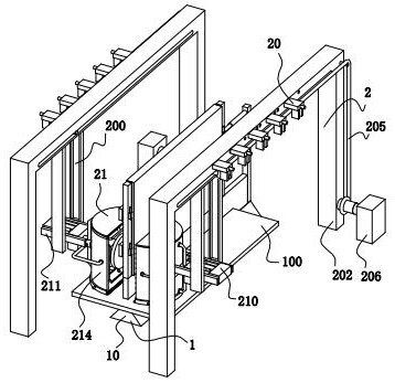
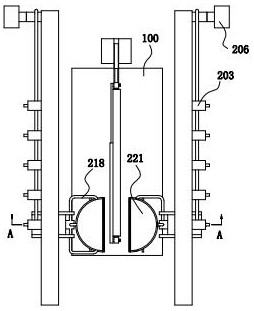
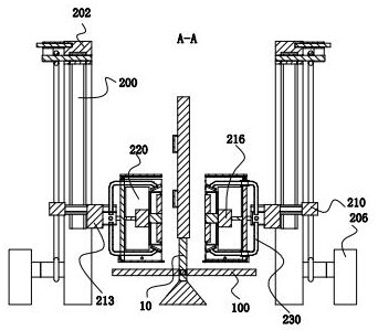
[0036] refer to figure 1 , figure 2 with image 3 , a concrete precast slab surface grinding device, including a fixing mechanism 1 and a grinding mechanism 2, the fixing mechanism 1 and the grinding mechanism 2 are placed on the ground, and the grinding mechanism 2 is symmetrically arranged front and rear with respect to the fixing mechanism 1.

[0037] refer to figure 1 , Image 6 with Figure 7 , the fixed mechanism 1 includes a fixed base 10, a fixed...


PUM


Abstract

The invention relates to the field of concrete precast slab surface machining, in particular to a concrete precast slab surface layer polishing device which comprises a fixing mechanism and a polishing mechanism, and on the basis that the function of changing the position of a polishing part is achieved, an execution part mainly plays a role in limiting the single-time moving distance of the polishing part, and the polishing part can be used for polishing the surface layer of the concrete precast slab. The situation that the nth grinding part and the (n + 1) th grinding part of the surface of the concrete prefabricated slab are overlapped, and consequently the surface of the concrete prefabricated slab is in a non-uniform grinding state is avoided, and the dust collection plates are arranged in multiple directions, so that the dust collection range is enlarged, dust collection dead corners are reduced, and the dust collection efficiency is improved. The dust generated by polishing is timely sucked by the dust suction machine to the greatest extent, the probability that the dust is scattered into the working environment is reduced, a closed space can be formed when the cover shell is in contact with the concrete precast slab, the effect of covering the dust is achieved, and then the dust suction machine can timely suck the dust and reduce the probability that the dust is scattered all around.

Description

technical field [0001] The invention relates to the field of surface processing of prefabricated concrete slabs, in particular to a surface grinding device for prefabricated concrete slabs. Background technique [0002] The prefabricated slab is the floor slab, which refers to the concrete prefabricated parts that are produced and processed in the prefabricated field and directly transported to the construction site for installation. Surface flatness and assembly requirements. [0003] The Chinese utility model patent whose publication number is CN208409424U in the prior art discloses a floor grinding device for building construction. This utility model device controls the lifting height of the floor in the vertical direction through a screw lifting device, and is driven by a rotating motor. The grinding disc rotates in the vertical direction, and the floor surface is polished by the grinding disc. Although the device has realized the purpose of mechanized operation grindin...

Claims


Application Information

Patent Timeline
Patent Type & Authority Applications(China)
IPC IPC(8): B24B7/22B24B55/06B24B47/06B24B41/06B24B47/12
Inventor 张梅
Owner 徐州奥星新型建材有限公司
Why Eureka
Try Eureka