Positioning device for skull drilling

A positioning device and skull technology, applied in the direction of bone drill guidance, stereotaxic surgical instruments, medical science, etc., can solve the problems of cervical traction treatment failure and patient pain

Active Publication Date: 2020-09-15
THE SECOND XIANGYA HOSPITAL OF CENT SOUTH UNIV
View PDF6 Cites 2 Cited by
  • Summary
  • Abstract
  • Description
  • Claims
  • Application Information

AI Technical Summary

Problems solved by technology

It further leads to the failure of cervical traction treatment, which brin

Method used


Image

  • Positioning device for skull drilling
  • Positioning device for skull drilling
  • Positioning device for skull drilling

Examples


Embodiment Construction

[0029] The following will clearly and completely describe the technical solutions in the embodiments of the present invention with reference to the accompanying drawings in the embodiments of the present invention. Obviously, the described embodiments are only some, not all, embodiments of the present invention. Based on the embodiments of the present invention, all other embodiments obtained by persons of ordinary skill in the art without making creative efforts belong to the protection scope of the present invention.

[0030] In order to enable those skilled in the art to better understand the solution of the present invention, the present invention will be further described in detail below in conjunction with the accompanying drawings and specific embodiments.

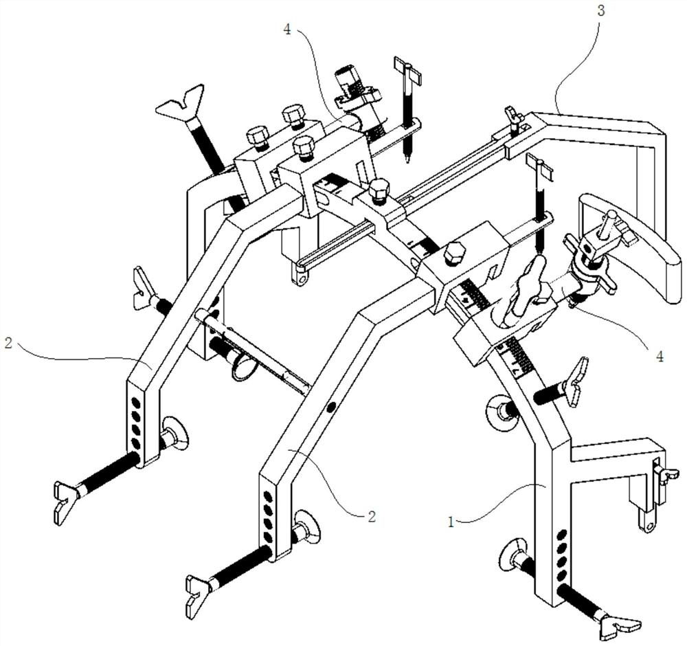
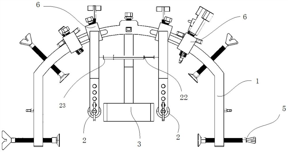
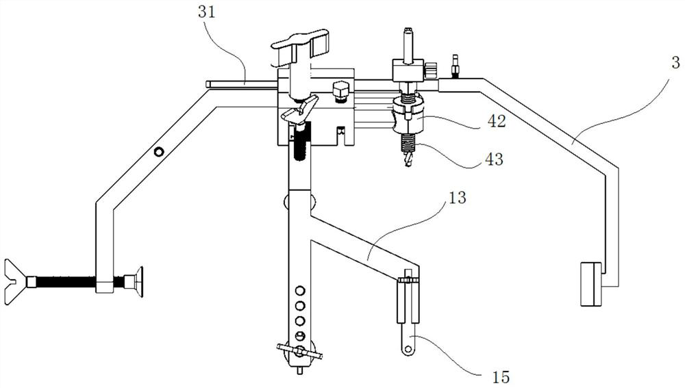
[0031] Please refer to Figure 1 to Figure 9 , figure 1 Schematic diagram of the structure of the skull drilling positioning device provided by the present invention; figure 2 for figure 1 Front view of the midd...


PUM


Abstract

The invention discloses a positioning device for skull drilling. The positioning device comprises a main mounting frame, front fixing rods and a rear fixing rod. During use, the main mounting frame isarranged above the head of a patient, and extends in the left-right direction of the patient; the main mounting frame is fixed to the head of the patient; the front fixing rods are movably connectedwith the main mounting frame; one end of each front fixing rod extends to the rear of the main mounting frame, and is used for positioning a drilling point, and the other end of each front fixing rodextends to the front of the head of the patient, is suspended in front of the head of the patient, and is used for being fixed to the head of the patient; one end of the rear fixing rod is movably connected with the main mounting frame, and the other end of the rear fixing rod extends to the rear of the head of the patient and is used for supporting the head of the patient from the rear portion; adrill bit fixing rod is movably connected onto the main mounting frame, and a drill bit can be effectively positioned by adjusting the position of the drill bit fixing rod; and the drill bit is arranged in the drill bit fixing rod, and drills the drilling position located by the front fixing rods, so that the accuracy of the drilling position can be guaranteed.

Description

technical field [0001] The invention relates to the technical field of surgical equipment, in particular to a skull drilling positioning device. Background technique [0002] Patients with severe cervical fracture and dislocation are often accompanied by spinal cord injury, and most of them are accompanied by multiple injuries. If not treated in time, severe cases may cause spinal cord injury, edema spread and even life-threatening. Therefore, clinicians need to give reasonable internal fixation in time to reconstruct the stability and reduce spinal cord injury. [0003] Preoperative cranial distraction has a long history of clinical application. This operation is simple and practical, and plays an important role in maintaining the stability of the fracture and maximizing the reduction of the cervical sequence. Preoperative cranial traction can restore the normal sequence of the fractured and dislocated cervical vertebrae, avoid secondary damage to the spinal cord, and al...

Claims


Application Information

Patent Timeline
IPC IPC(8): A61B17/17A61B90/11
CPCA61B17/171A61B17/1739A61B90/11
Inventor 张杰张博友王李佳万奇徐姣王静成
Owner THE SECOND XIANGYA HOSPITAL OF CENT SOUTH UNIV
Why Eureka
Try Eureka