
Ablation catheter and ablation device for image-guided ablation

An ablation catheter and image-guided technology, applied in the field of ablation catheters and ablation equipment, can solve problems such as excessive ablation, inaccurate temperature detection, incomplete ablation, etc., and achieve the effect of preventing excessive ablation, complete ablation, and preventing recurrence

Inactive Publication Date: 2020-09-15
THE BEST ABLATION & INT TECH INST (NANJING) CO LTD
View PDF5 Cites 2 Cited by
  • Summary
  • Abstract
  • Description
  • Claims
  • Application Information

AI Technical Summary

Problems solved by technology

Similarly, in the ablation process of the existing cryoablation needle, there is also the problem of inaccurate temperature detection. At this time, if the ablation is still performed according to the originally planned ablation conditions, it may lead to incomplete ablation or excessive ablation.

Method used


Image

  • Ablation catheter and ablation device for image-guided ablation
  • Ablation catheter and ablation device for image-guided ablation
  • Ablation catheter and ablation device for image-guided ablation

Examples


no. 1 example

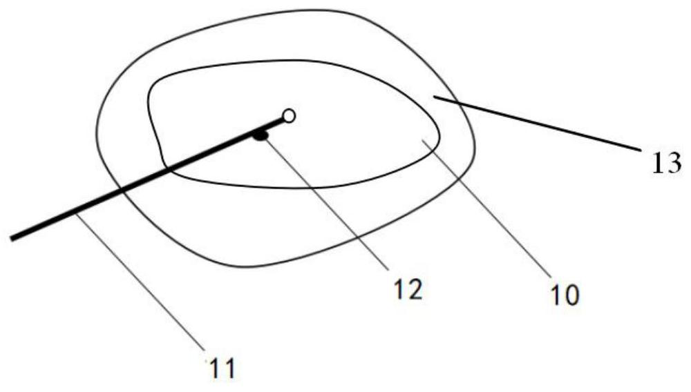
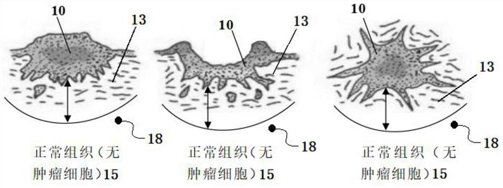
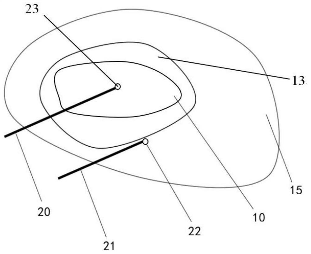
[0040] The ablation catheter and ablation equipment provided by the invention are suitable for image-guided ablation operations. Such as image 3 and Figure 4As shown, the radiofrequency catheter provided by the present invention has an independent ablation probe 20 and a temperature measurement probe 21. By placing the ablation probe 20 in the tissue to be ablated 10 (such as a tumor), and placing the temperature measurement probe 21 It is positioned outside the junction area 13 between the tissue to be ablated 10 and the normal tissue 15 (of tumor tissue and normal tissue), and the actual temperature of the junction area of ​​the tissue to be ablated 10 is measured accurately in real time, so that the implementation of the ablation operation can be precisely controlled, so that the to-be-ablated The ablated tissue is completely ablated, preventing the recurrence of the tissue to be ablated, and can effectively protect the normal tissue and prevent excessive ablation.

[0...

no. 2 example

[0057] The ablation catheter and ablation device provided by the second embodiment are also suitable for image-guided cryoablation. Wherein, the radiofrequency catheter has an independent ablation probe 40 and a temperature measurement probe 51, and by piercing the ablation probe 40 into the tissue to be ablated (such as a tumor), and positioning the temperature measurement probe 51 between the tissue to be ablated 10 and the normal Outside the junction area 13 of the tissue 15 (tumor tissue and normal tissue), the actual temperature of the junction area of ​​the tissue to be ablated 10 is measured accurately in real time, so that the implementation of the ablation operation can be precisely controlled, so that the tissue to be ablated is completely ablated and prevents the tissue from being ablated. Tissue recurrence can effectively protect normal tissue and prevent excessive ablation.

[0058] In this example, if Figure 6 and Figure 7 As shown, the radio frequency cathet...


PUM


Abstract

The invention discloses an ablation catheter and an ablation device for image-guided ablation. The ablation catheter comprises a slender catheter, and a first catheter branch and a second catheter branch are arranged at the far end of the catheter main body; an ablation probe is arranged at the far end of the first catheter branch; a temperature measuring probe is arranged at the far end of the second catheter branch; and a control handle is arranged at the near end of the catheter main body. According to the ablation catheter, while the ablation probe is placed in a tissue to be ablated for ablation, a tiny temperature measuring probe can be positioned at the junction of the tissue to be ablated and normal tissues in a minimally invasive mode, the actual temperature of the junction area of the tissue to be ablated is accurately measured in real time, the temperature of the junction area of the tissue to be ablated can be accurately measured, and therefore implementation of an ablationoperation is accurately controlled.

Description

technical field [0001] The invention relates to an ablation catheter for image-guided ablation, and also relates to an ablation device including the ablation catheter, which belongs to the field of medical devices. Background technique [0002] Tumor hyperthermia refers to the use of a certain heating method to heat tumor tissue beyond its heat-resistant temperature to kill cancer cells, which includes hyperthermia and high-temperature thermal coagulation. Hyperthermia is to heat the tumor to 42.5-45°C and maintain it for a certain period of time (usually a few minutes to tens of minutes) to inhibit the growth of tumor tissue to achieve the purpose of treating cancer. The high-temperature thermal coagulation method is to heat the tumor tissue to a higher temperature (generally 60°C for an instant, or 54°C for one minute) to cause complete necrosis of the tumor. In the past ten years, with the development of microwave technology, especially implantable microwave technology, ...

Claims


Application Information

Patent Timeline
Patent Type & Authority Applications(China)
IPC IPC(8): A61B18/12A61B18/14A61B18/02A61B34/20
CPCA61B18/02A61B18/12A61B18/1402A61B18/1492A61B2018/00702A61B2018/00714A61B2018/00797A61B2018/0212A61B2018/0262A61B2018/0293A61B34/20A61B2034/2065
Inventor 董永华滕臬军
Owner THE BEST ABLATION & INT TECH INST (NANJING) CO LTD
Learn More