Multifunctional tray for dental implantation double scanning matching and jaw position recording and use method of multifunctional tray

A dual-scanning, multi-functional technology, applied in dentistry, dental prosthesis, dental radiology diagnosis, etc., can solve the problem of multiple visits of patients

Pending Publication Date: 2020-09-15
刘春煦
View PDF0 Cites 6 Cited by
  • Summary
  • Abstract
  • Description
  • Claims
  • Application Information

AI Technical Summary

Problems solved by technology

[0005] The purpose of the present invention is to provide a multi-functional tray for dental implant double-scan matching and jaw position recording and a method of use. The existing implant technology requires patients to visit the doctor multiple times before the guide plate implant surgery can be performed

Method used


Image

  • Multifunctional tray for dental implantation double scanning matching and jaw position recording and use method of multifunctional tray
  • Multifunctional tray for dental implantation double scanning matching and jaw position recording and use method of multifunctional tray
  • Multifunctional tray for dental implantation double scanning matching and jaw position recording and use method of multifunctional tray

Examples


Embodiment 1

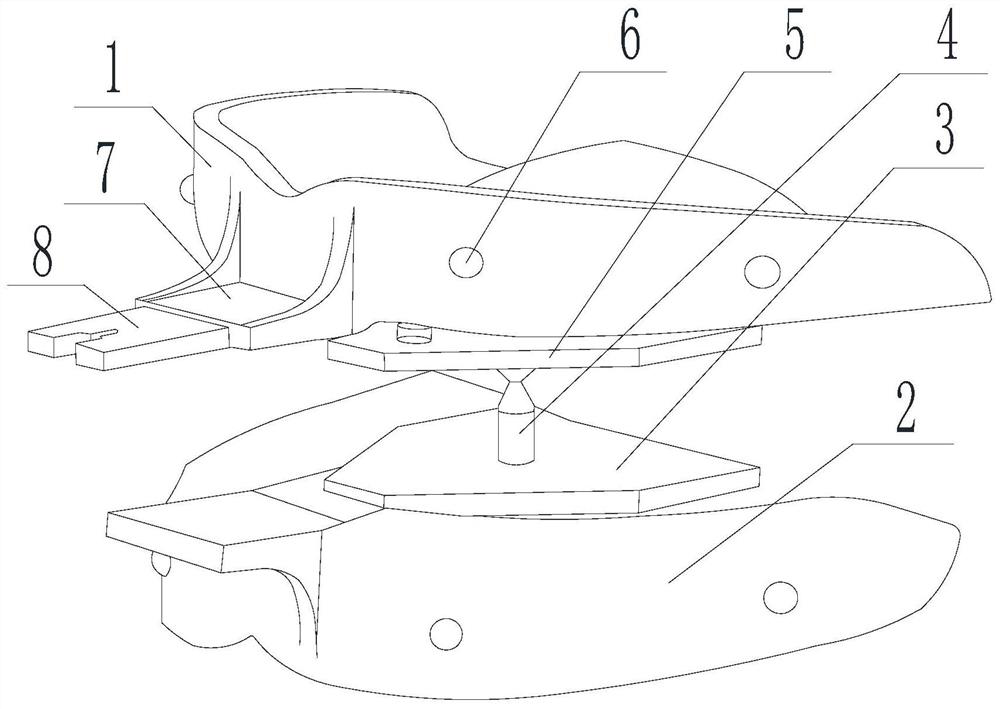
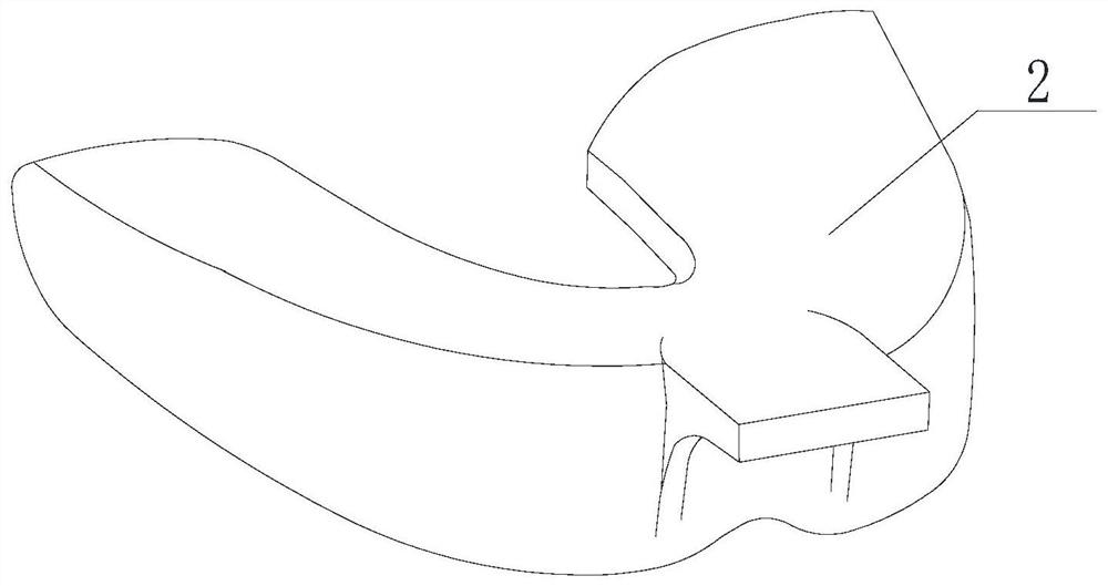
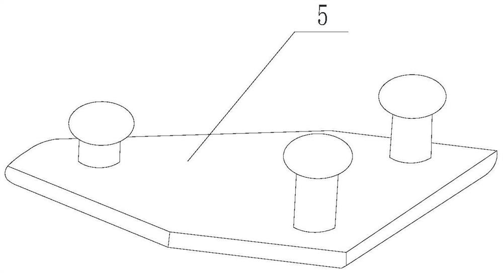
[0061] Such as Figure 1-Figure 4 As shown, the dental implant dual-scan matching multi-function tray with jaw position recording includes the upper jaw tray main body 1 and the lower jaw tray main body 2, and the upper jaw tray main body 1 and the lower jaw tray main body 2 are respectively connected with the maxillary tooth area and the mandibular tooth area in the oral cavity. The area matching also includes the upper jaw arch plate 5 and the lower jaw arch plate 3 which are detachably connected to the upper jaw tray main body 1 and the lower jaw tray main body 2 respectively. When the tray is used, the upper jaw arch plate 5 and the lower jaw arch plate 3 are respectively placed on the upper teeth The inner side of the area and the inner side of the mandibular teeth area. Specifically, the upper jaw tray main body 1 includes a U-shaped bottom plate, and a U-shaped side plate is arranged on the U-shaped bottom plate to cooperate with the upper jaw teeth area. The U-shaped bo...

Embodiment 2

[0079] Such as Figure 1-Figure 4 As shown, this embodiment is based on Embodiment 1, and further includes a height adjustment screw 4, which is detachably arranged between the maxillary arch plate 5 and the mandibular arch plate 3; the mandibular arch plate 3 is provided with A threaded through hole for cooperation with the height adjustment screw 4; the bottom of the maxillary arch plate 5 is provided with a groove for cooperation with the height adjustment screw 4.

[0080] In this embodiment, during clinical use, the mandibular tray main body 2 is worn in the mouth, and the patient's occlusal height is adjusted through the height adjustment screw 4: twist the height adjustment screw 4 into the threaded through hole of the mandibular tray main body 2, and put it in the mouth When the height is adjusted by rotating the height adjustment screw 4 so that the top of the height adjustment screw 4 is in contact with the maxillary arch plate 5 on the upper jaw tray main body 1, th...

Embodiment 3

[0082] Such as Figure 1-Figure 4 As shown, this embodiment is based on Embodiment 1 or Embodiment 2. The upper jaw tray main body 1 and the lower jaw tray main body 2 are provided with a handle 7 at the center of the labial side, and the universal joint connection device 8 and the handle 7 can be Detachable connection.


PUM


Abstract

The present invention discloses a multifunctional tray for dental implantation double scanning matching and jaw position recording and a use method of the multifunctional tray. The tray comprises an upper jaw tray main body and a lower jaw tray main body, the upper jaw tray main body and the lower jaw tray main body are respectively matched with an upper jaw tooth area and a lower jaw tooth area in an oral cavity, a plurality of radiation blocking devices are respectively arranged in the upper jaw tray main body and the lower jaw tray main body, a universal joint connecting device is detachably arranged at a central position of a labial side on the upper jaw tray main body, the multifunctional tray also comprises an upper jaw arch plate and a lower jaw arch plate detachably connected withthe upper jaw tray main body and the lower jaw tray main body respectively, and when the tray is used, the upper jaw arch plate and the lower jaw arch plate are respectively arranged at an inner sideof the upper jaw tooth area and an inner side of the lower jaw tooth area. The tray is suitable for implantation operations of patients with metal artifacts, too few natural teeth or no natural teeth,and also can avoid a problem that guide plate implantation operations can be performed only by requiring the patients to see a doctor for many times in an existing implantation technology.

Description

technical field [0001] The invention relates to the technical field of dental implants, in particular to a multifunctional tray for double-scan matching and jaw position recording for dental implants and a method of use thereof. Background technique [0002] As one of the most commonly used digital surgical techniques in the field of dentistry, implant surgical guides are gradually accepted by physicians and patients as the preferred surgical auxiliary guidance technology for various simple and complex cases. The implant surgery guide can accurately guide the fixed point, depth, reaming, and implant placement during the implant implantation process. The implantation under the guide plate is not only more accurate, but also saves the operation time, reduces the difficulty of the operation, liberates the brain of the doctor, and makes the operation process transition from experience to digitalization. [0003] Before the design of the implant surgery guide, after the patient ...

Claims


Application Information

Patent Timeline
IPC IPC(8): A61C8/00A61C9/00A61B6/14A61B6/03
CPCA61C8/009A61C9/0006A61B6/032A61C9/0053A61B6/512
Inventor 刘春煦
Owner 刘春煦
Why Eureka
Try Eureka