A condition-independent identification method of milling cutter wear state based on spindle drive current

A technology of spindle drive and wear state, applied in the direction of manufacturing tools, metal processing equipment, metal processing machinery parts, etc., can solve problems such as interfering with the normal processing of machine tools, and achieve the effect of reducing workpiece scrap rate and machine tool failure rate, and reducing factory costs.

Active Publication Date: 2022-02-15
BEIJING UNIV OF TECH
View PDF6 Cites 0 Cited by
  • Summary
  • Abstract
  • Description
  • Claims
  • Application Information

AI Technical Summary

Problems solved by technology

However, the indirect monitoring method needs to install the sensor in the machining area of ​​the machine tool to collect cutting force and vibration signals, which interferes with the normal machining of the machine tool, and is not suitable for online identification of milling cutter wear status under complex working conditions and variable cutting conditions.

Method used


Image

  • A condition-independent identification method of milling cutter wear state based on spindle drive current
  • A condition-independent identification method of milling cutter wear state based on spindle drive current
  • A condition-independent identification method of milling cutter wear state based on spindle drive current

Examples


Embodiment Construction

[0019] The present invention will be further described in detail below in conjunction with the accompanying drawings. The following examples are only used to explain the present invention, and do not constitute a limitation to the protection scope of the present invention.

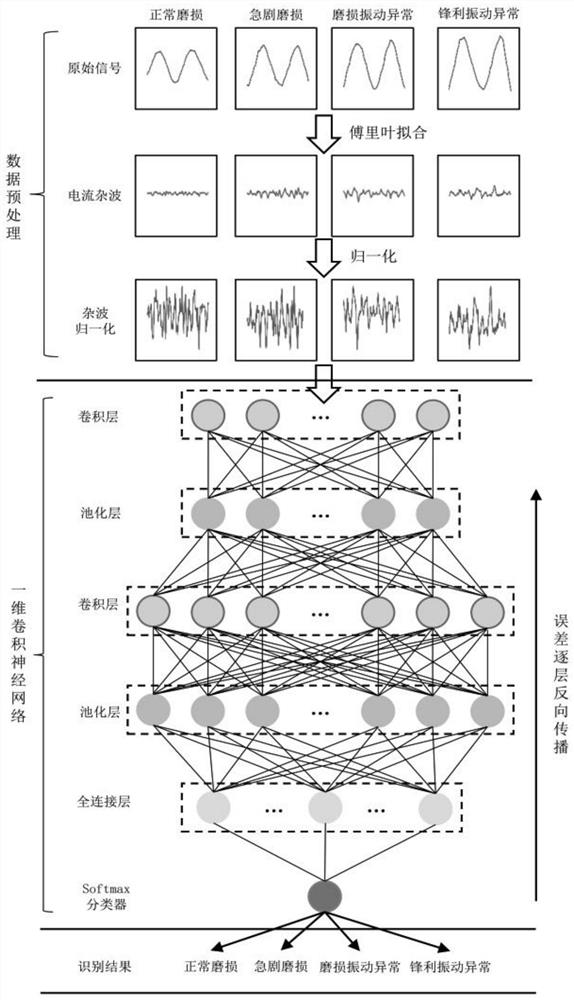
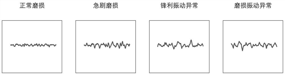
[0020] Such as figure 1 Shown is the flow chart of the identification of tool wear state in the present invention. The present invention provides a milling cutter wear state identification method based on spindle driving current that is independent of working conditions, including the following steps:

[0021] a. Collect the original signal of the spindle drive current and the vibration signal of the spindle during metal milling;

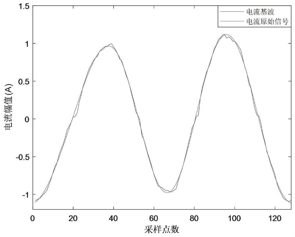
[0022] b. Fit the original signal of the collected spindle drive current through Fourier series fitting to obtain a spindle drive current clutter signal that has nothing to do with the working condition;

[0023] c. Normalize the acquired clutter signals so that all signal amp...


PUM


Abstract

The invention discloses a milling cutter wear state identification method based on spindle drive current which is independent of working conditions. The method is based on the test results of irregular clutter components in the spindle drive current signal due to tool wear and abnormal vibration. The method utilizes Fourier Series fitting decomposes the spindle drive current waveform into harmonic components reflecting quasi-static changes in current RMS and current clutter signals reflecting the wear state of the milling cutter edge and flank and abnormal vibration, and then input the current clutter signals To the convolutional neural network for milling cutter state feature extraction and classification. Through the above method, the present invention can realize the online accurate identification of the milling cutter state under complex working conditions and variable cutting conditions, laying a foundation for predicting the remaining life of the milling cutter and scientifically and rationally formulating milling cutter replacement rules under complex working conditions.

Description

technical field [0001] The invention relates to a method for identifying the wear state of a milling cutter based on a spindle drive current irrelevant to working conditions, and belongs to the technical field of state detection of numerically controlled machine tools. Background technique [0002] During the metal milling process, the flank and cutting edge of the milling cutter will gradually accumulate wear due to cutting stress and workpiece friction. At the same time, there will be relative vibration between the tool and the workpiece. Tool wear and abnormal vibration not only directly affect the quality and machining accuracy of the machined surface, but also increase the surface roughness of the workpiece. If it increases, it will cause serious damage to the tool, scrap the workpiece, damage the machine tool, and even affect the normal production of the factory, bringing economic losses to the enterprise. At present, the tool condition monitoring methods at home and ...

Claims


Application Information

Patent Timeline
Patent Type & Authority Patents(China)
IPC IPC(8): B23Q17/09
CPCB23Q17/0957
Inventor 王民宋铠钰刘利明
Owner BEIJING UNIV OF TECH
Why Eureka
Try Eureka