Automatic passing-through type grinding machine

A grinding machine, automatic technology, applied in the direction of grinding machine, grinding machine parts, grinding feed movement, etc., can solve the problem of low processing efficiency

Inactive Publication Date: 2020-09-15
惠州市通达磁材科技有限公司
View PDF0 Cites 2 Cited by
  • Summary
  • Abstract
  • Description
  • Claims
  • Application Information

AI Technical Summary

Problems solved by technology

[0003] Existing grinding machines often use manpower to adjust the position of the jig to process the workpiece. When manpower adjustment is used for processing, the operator often needs to use both hands to adjust the moving mechanism, so as to drive the workpiece to move. As a result, the grinding me

Method used


Image

  • Automatic passing-through type grinding machine
  • Automatic passing-through type grinding machine
  • Automatic passing-through type grinding machine

Examples


Embodiment 1

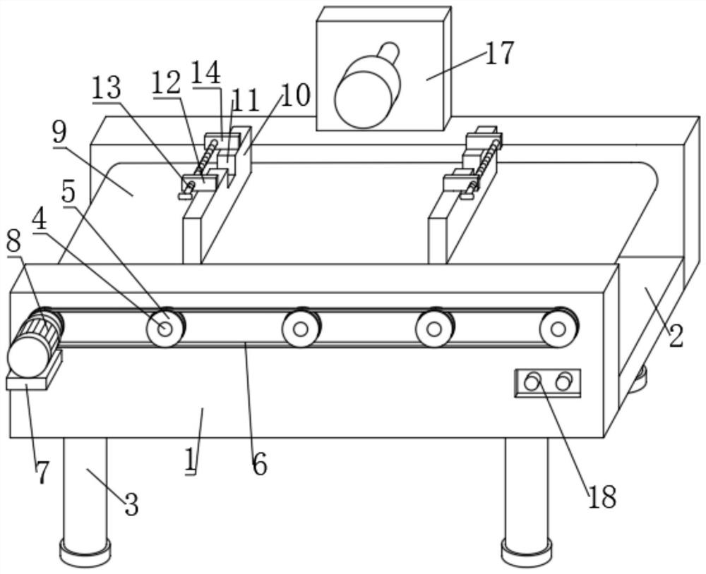
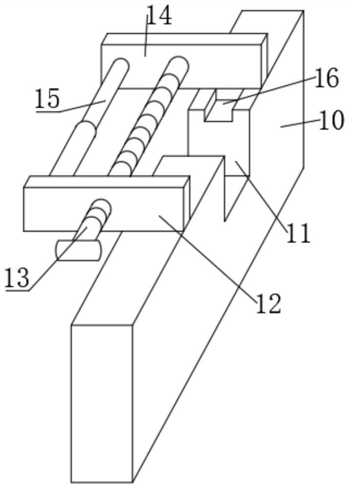
[0021] refer to Figure 1-3 , an automatic through-type grinding machine, including a bottom plate 2, two side plates 1 are fixed symmetrically by bolts at both ends of the bottom plate 2, and the front end of one side plate 1 is connected with a plurality of straight shafts 4 through hinge rotation, and the front ends of the straight shafts 4 are connected by bolts The pulley 5 is fixed, and the same belt 6 is sleeved on multiple pulleys 5. The rear end of the straight shaft 4 is welded with a transmission roller, and the transmission roller is arranged between two side plates 1. The transmission rollers are sleeved with For the same conveyor belt 9, the top of the conveyor belt 9 is provided with a fixing mechanism, the front end of the side plate 1 is fixed with a support plate 7 by bolts, the top of the support plate 7 is fixed with a motor 8, the output shaft of the motor 8 is connected with a reducer, and the output shaft of the reducer and One of the pulleys 5 is connec...

Embodiment 2

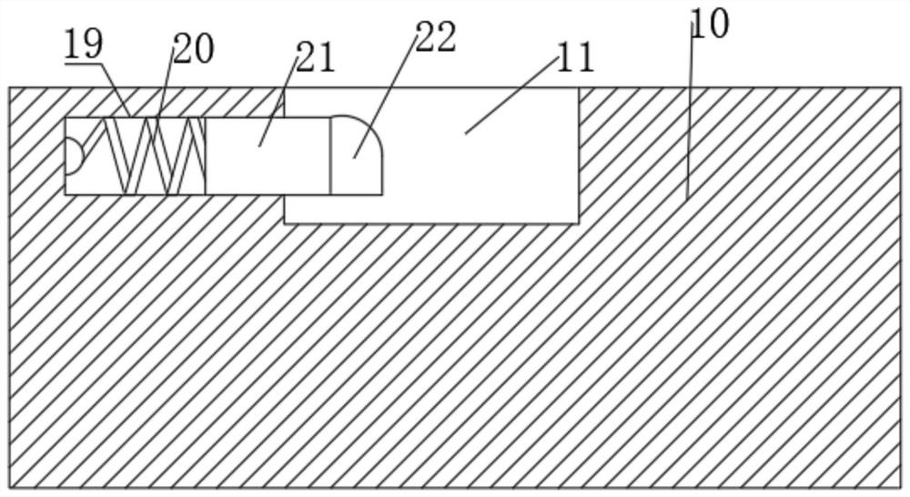
[0025] refer to Figure 1-3 , an automatic pass-through grinding machine, the fixed plate 10 is provided with a second chute 19, a spring 20 is welded in the second chute 19, a moving block 21 is welded at the rear end of the spring 20, and a limit block is welded at the rear end of the moving block 21 22. The top corner of the limit block 22 has rounded corners.

[0026] When in use, during the workpiece fixing process, the workpiece is first placed in the two slots 11, the spring 20 is compressed by force and exerts a reverse force on the moving block 21 due to its own elasticity, so that the limiting block 22 squeezes the workpiece, This facilitates subsequent operations of clamping and fixing the workpiece, and the top corners of the limiting block 22 are rounded, so that the workpiece can be placed in the slot 11 more conveniently.


PUM


Abstract

The invention discloses an automatic passing-through type grinding machine, which comprises a bottom plate, wherein two ends of the bottom plate are symmetrically fixed with two side plates; the frontend of one side plate is rotatably connected with a plurality of straight shafts; the front end of each straight shat is fixedly provided with a belt wheel; a plurality of belt wheels are sheathed with a belt; the rear end of each straight shaft is welded with a conveying roller; a plurality of conveying rollers are sheathed with a conveying belt; the top of the conveying belt is provided with afixing mechanism; the front end of one side plate is fixedly provided with a supporting plate and a control switch; the top of the supporting plate is fixedly provided with a motor; a motor output shaft is connected with a speed reducer; and the output shaft of the speed reducer is connected with one belt wheel. Since the control switch is arranged, a workpiece is fixed on a fixing mechanism in advance, a control motor can be controlled through the control switch to carry out positive and negative rotation, the motor drives the belt wheels and the straight shafts to rotate, the plurality of belt wheels rotate together through belt transmission so as to drive the conveying rollers and the conveying belt to rotate, the fixing mechanism moves in a horizontal direction, and the workpiece on the fixing mechanism is automatically polished and processed.

Description

technical field [0001] The invention relates to the technical field of mechanical equipment, in particular to an automatic pass-through grinder. Background technique [0002] There are many kinds of mechanical equipment. When the mechanical equipment is running, some of its parts and even itself can perform different forms of mechanical movement. Mechanical equipment consists of driving devices, transmission devices, transmission devices, working devices, braking devices, protective devices, lubrication systems, cooling systems, etc., including grinding machines, which use abrasive tools to grind workpieces to obtain the required Machine tools with shape, size and precision machining surface, grinding machine can process hardened steel, cemented carbide and other materials with high hardness, as well as materials with high brittleness such as glass and granite. [0003] Existing grinding machines often use manpower to adjust the position of the jig to process the workpiece....

Claims


Application Information

Patent Timeline
IPC IPC(8): B24B27/00B24B41/06B24B41/00
CPCB24B27/00B24B27/0092B24B41/005B24B41/06
Inventor 陈中王绪强刘荣
Owner 惠州市通达磁材科技有限公司
Why Eureka
Try Eureka