
Walking control system and method and mechanical device

A technology of walking control and walking mechanism, which is applied to mechanically driven excavators/dredgers, earth movers/shovels, construction, etc., and can solve problems such as unfavorable driver operation, blocked driver's vision, uncoordinated movements, etc. , to avoid line-of-sight obstruction, reduce the volume of the cab, and increase the space

Inactive Publication Date: 2020-09-15
QINGDAO LOVOL EXCAVATOR
View PDF4 Cites 0 Cited by
  • Summary
  • Abstract
  • Description
  • Claims
  • Application Information

AI Technical Summary

Problems solved by technology

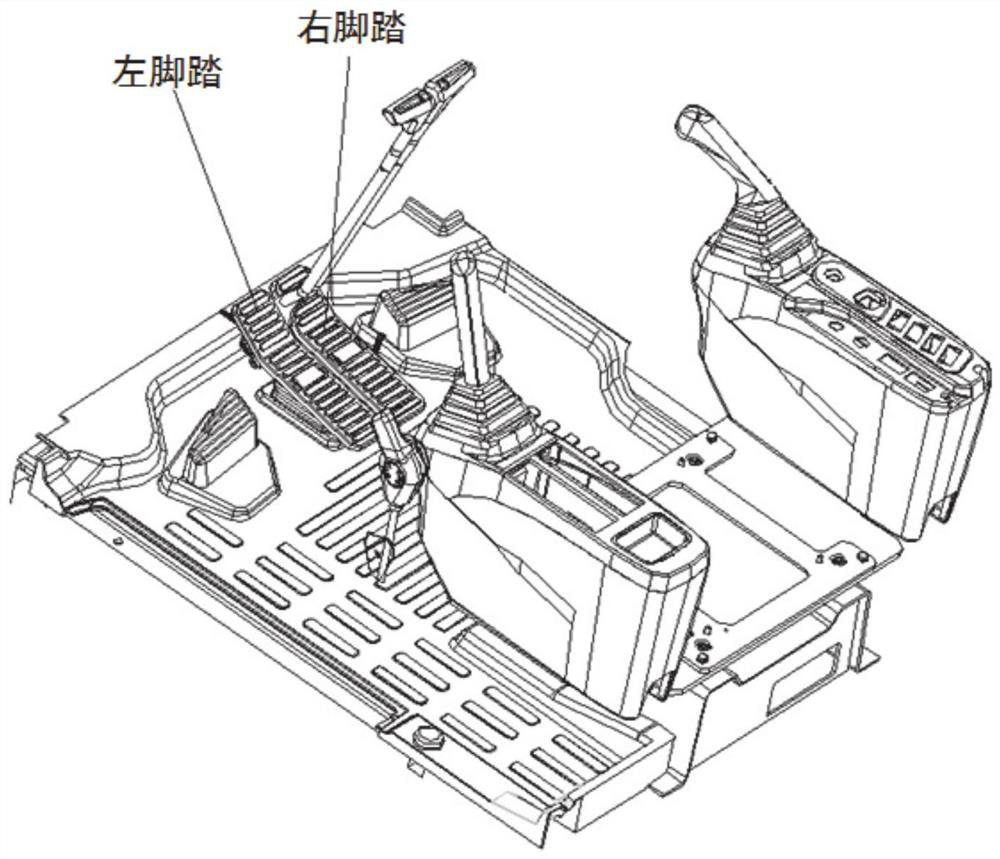
[0004] The inventors have found that currently the operation methods of large crawler-type construction machinery such as excavators mostly use both hands and feet. The driver's feet control the pedals to control the overall movement of the construction machinery, and the hands control the joystick to control the construction machinery. However, when the operation arm moves while moving, the driver's hands and feet need to move at the same time, and the hands and feet are in a tense state for a long time, which is easy to cause operation errors due to uncoordinated movements; in addition, the left and right walking pedals are located on the body In front of the oblique front, the feet need to be kept above the pedals at all times, which will block the driver's vision of the low places for a long time, which is not conducive to the driver's operation

Method used


Image

  • Walking control system and method and mechanical device
  • Walking control system and method and mechanical device
  • Walking control system and method and mechanical device

Examples


Embodiment 1

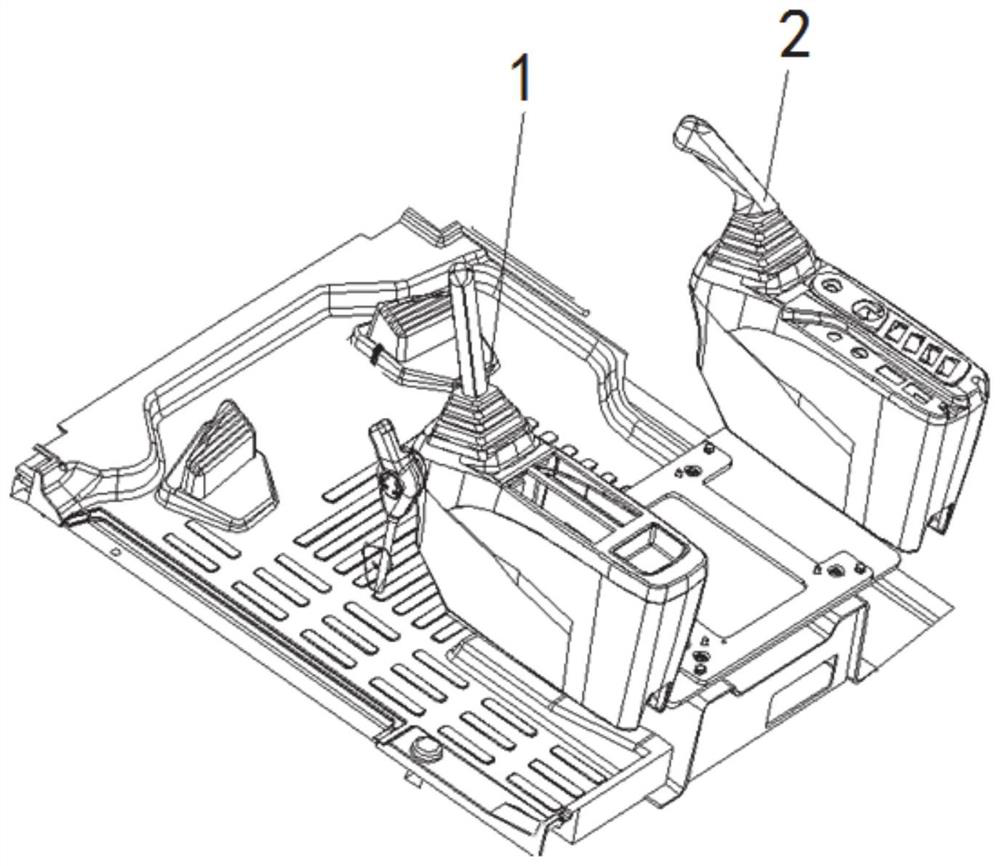
[0036] In a typical implementation of the present disclosure, such as Figure 1-Figure 4 As shown, a walking control system is proposed.

[0037] It mainly includes the control handle and the controller. The gripping area of ​​the control handle is equipped with a rolling wheel, which is equipped with a rolling potentiometer. When the rolling wheel is rolling, it can drive the rolling potentiometer to output different potential signals. This potential signal controls the electric control valve of the hydraulic system, thereby changing the output power of the hydraulic system to the traveling mechanism, thereby changing the working state of the traveling mechanism, and controlling the driving direction and driving speed of the mechanical equipment through the traveling mechanism.

[0038] compared to if figure 1 In the traditional walking control system, in this embodiment, the roller is used as the control element of the walking mechanism, installed on the control handle, and...

Embodiment 2

[0053] In another typical embodiment of the present disclosure, as Figure 2-Figure 4 As shown, a walking control method is proposed.

[0054] Utilize walking control system as described in embodiment 1, and comprise the following steps:

[0055] The roller starts to rotate from an initial position driven by an external force, and the roller is driven by an external force to rotate in a first direction or in a second direction opposite to the first direction;

[0056] The rolling potentiometer obtains the corresponding potential signals in the first direction and the second direction in real time, and sends the corresponding signals to the controller;

[0057] The controller controls the action of the electric control valve according to the signal of the scroll potentiometer, and changes the action state of the traveling mechanism.

[0058] Further, the scroll wheel and the rolling potentiometer correspond to form a set of control structures, and there are two sets of contro...

Embodiment 3

[0064] In yet another exemplary embodiment of the present disclosure, such as Figure 2-Figure 4 As shown, a mechanical device is proposed, which includes the walking control system as described in Embodiment 1.

[0065] It also includes a traveling mechanism and a hydraulic system, the walking control system is connected to the traveling mechanism through the hydraulic system, and changes the running state of the traveling mechanism by controlling the output of the hydraulic system;

[0066] There are two control handles of the walking control system, and each control handle corresponds to a roller and a scroll potentiometer. The traveling mechanism includes two sets of actuators, and each roller and the corresponding scroll potentiometer control a set the action of the component;

[0067] The actuator is a crawler belt, and a left crawler belt and a right crawler belt are respectively matched on both sides of the mechanical equipment;

[0068] The hydraulic system includes...


PUM


Abstract

The invention provides a walking control system and method and a mechanical device. The walking control system comprises control handles and a controller. The holding portion of each control handle isprovided with a rolling wheel. The rolling wheel is provided with a rolling potentiometer in a matched manner, wherein the rolling potentiometers are electrically connected with the controller. The controller is used for obtaining signals of the potentiometers and controlling an electrical control valve of a hydraulic system to act according to the signals, and then a walking mechanism of equipment is controlled to act. Thumb rolling wheels are arranged on the control handles to replace a walking stepping mechanism so as to control the mechanical device to walk, and the thumb rolling wheels are used for operating the walking mechanism of the equipment. Control over actions of the whole vehicle, such as the walking mechanism and an operation arm, is achieved through the two control handles, so that the space of a drive cab is expanded, and cost is lowered.

Description

technical field [0001] The present disclosure relates to the field of mechanical equipment, in particular to a walking control system, method and mechanical equipment. Background technique [0002] The statements in this section merely provide background information related to the present disclosure and may not necessarily constitute prior art. [0003] With the increasing demand for engineering construction and facility construction, the operational performance requirements for mechanical equipment, especially construction machinery such as excavators, are also getting higher and higher; existing parts of large crawler construction machinery such as excavators Manipulate mechanical structures such as figure 1 As shown, it includes the left and right walking pedals. By pushing forward or pulling the pedals back, the crawler on the corresponding side can be controlled to advance or retreat, so as to realize the overall forward, backward, left turn, right turn and other actio...

Claims


Application Information

Patent Timeline
Patent Type & Authority Applications(China)
IPC IPC(8): E02F9/20E02F9/22E02F3/04
CPCE02F3/04E02F9/2004E02F9/225E02F9/2253E02F9/2264
Inventor 吴现卫陈维雄陈会君邹梓玲刘虹
Owner QINGDAO LOVOL EXCAVATOR
Learn More