Double-degree-of-freedom torque motor based on annular air gap

A torque motor and degree of freedom technology, applied in the field of electro-hydraulic servo control components, can solve the problem that torque motors cannot meet the feedback requirements at the same time, and achieve the effects of large rotation angle, increased inclination angle, and low processing cost.

Pending Publication Date: 2020-09-15
ZHEJIANG UNIV OF TECH
View PDF0 Cites 0 Cited by
  • Summary
  • Abstract
  • Description
  • Claims
  • Application Information

AI Technical Summary

Problems solved by technology

[0007] In order to overcome the shortcomings of the existing torque motors that cannot simultaneously satisfy the requirements of feedback, large inclination, small air gap, and long stroke, the present invention provides a dual-degree-of-freedom torque motor based on an annular air gap

Method used


Image

  • Double-degree-of-freedom torque motor based on annular air gap
  • Double-degree-of-freedom torque motor based on annular air gap
  • Double-degree-of-freedom torque motor based on annular air gap

Examples


Embodiment Construction

[0028] The present invention will be further described below in conjunction with the accompanying drawings.

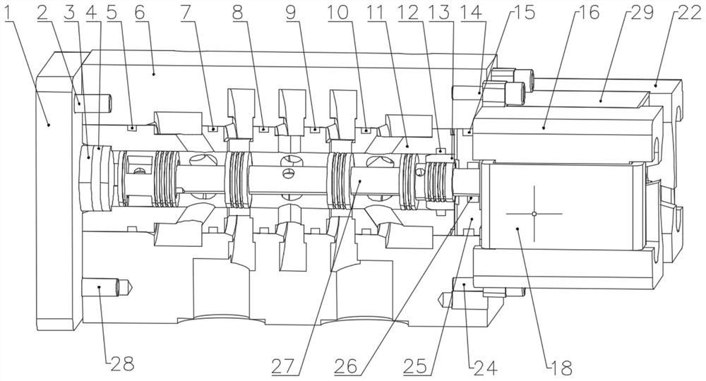
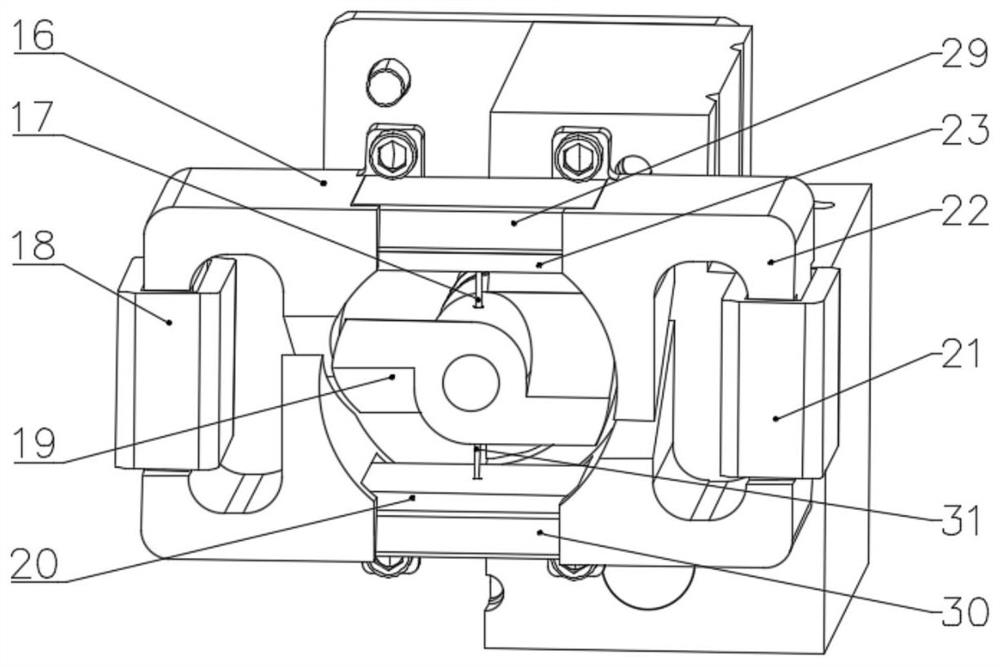
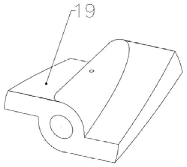
[0029] refer to Figure 1 ~ Figure 1 0, a new dual-degree-of-freedom torque motor based on an annular air gap, including a new dual-degree-of-freedom torque motor and a hydraulically amplified part. The novel dual-degree-of-freedom torque motor consists of a first yoke 16, a second yoke 22, an armature 19, a first permanent magnet 29, a second permanent magnet 30, a first spring rod 17, a second spring rod 31, and a first coil 18. , the second coil 21, the first spring top plate 20, the second spring top plate 23 and fixing screws and the like.

[0030]The first yoke 16 and the second yoke 22 are symmetrically arranged on both sides of the armature 19, and the first yoke 16 and the second yoke 22 are in a mirror image relationship on the vertical plane passing through the rotating shaft of the armature 19, and the direction close to the armature 19 is Inside, and vic...


PUM


Abstract

The invention discloses a double-degree-of-freedom torque motor based on an annular air gap. The double-degree-of-freedom torque motor based on the annular air gap comprises an armature with a rotating shaft arranged along a horizontal plane, wherein the armature comprises two inclined wing surfaces which are arrayed by 180 degrees with an axis perpendicular to the horizontal plane and vertical upwards as a central axis; the two sides of the armature are symmetrically provided with a first yoke and a second yoke, the inner sides of the two yokes are arc-shaped, the outer sides of the two yokesare respectively wound with coils, and the inner side wall surfaces of the two yokes are respectively provided with inclined slots with the same inclination direction relative to the rotating shaft as the side ends of the adjacent inclined wing surfaces of the armature; the inclined wing side end of the armature is an arc surface, the inclined wing side end of the armature spans the inclined slots and forms four working air gaps with the two arc surfaces, divided by the corresponding inclined slot, of the first yoke and the two arc surfaces, divided by the corresponding inclined slot, of thesecond yoke; permanent magnets are respectively erected at the upper parts and the lower parts of the inner sides of the two yokes; and the upper ridge surface and the lower ridge surface of the armature are connected with spring rods, and the ball ends of the spring rods are movably inserted into ball sockets of spring top plates respectively.

Description

technical field [0001] The invention relates to the field of electro-hydraulic servo control components, in particular to a two-degree-of-freedom torque motor. Background technique [0002] Since its appearance in the 1940s, electro-hydraulic servo control technology has occupied a high-end position in electromechanical transmission and control technology due to its high power-to-weight ratio, large output force (torque) and excellent static and dynamic characteristics. Its core competitiveness has important applications in various key occasions such as aerospace, military weapons, ships, large power stations, steel, material testing machines and vibration tables. In the electro-hydraulic servo control system, the electro-hydraulic servo valve plays the role of electromechanical conversion and signal amplification, which has a decisive impact on the performance of the entire system to a large extent. [0003] In order to obtain ideal static and dynamic characteristics, peop...

Claims


Application Information

Patent Timeline
Patent Type & Authority Applications(China)
IPC IPC(8): F15B15/08F15B15/20F15B13/02F16K11/07
CPCF15B13/021F15B15/08F15B15/20F15B2215/30F16K11/0716
Inventor 孟彬戴铭柱刘备徐豪
Owner ZHEJIANG UNIV OF TECH
Why Eureka
Try Eureka