A distributed geared motor energy monitoring system and method

A technology for geared motors and monitoring systems, which is applied in control/regulation systems, signal transmission systems, electric components, etc., and can solve the problems of insufficient energy monitoring of distributed geared motors, increasing the service life of batteries in power supply units, and inability to provide on-site power supply, etc. , to reduce the cost of power supply deployment, prevent gears from getting stuck, and prolong the service life

Active Publication Date: 2022-08-02
HANGZHOU JIE DRIVE TECH
View PDF21 Cites 0 Cited by
  • Summary
  • Abstract
  • Description
  • Claims
  • Application Information

AI Technical Summary

Problems solved by technology

[0012] The present invention mainly solves the problem that the energy monitoring of the existing distributed deceleration motors is not comprehensive enough and the wiring is complicated, which leads to high cost; it provides a distributed deceleration motor energy monitoring system and method, which solves the on-site power supply problem of the deceleration motor and its monitoring equipment, and reasonably arranges Monitoring sensors make energy monitoring more comprehensive, prolong the service life of devices, reduce the complexity of wiring, and reduce the cost of power supply deployment
Through the acquisition device, the oil temperature, winding temperature and vibration amplitude of the motor are comprehensively monitored, which makes the operation of the distributed geared motor more reasonable. Through the power supply unit, the problem that the traditional distributed geared motor concentrator cannot provide on-site power supply is solved. At the same time, current detection and voltage monitoring adopt on-site monitoring. Compared with traditional electrical cabinet monitoring, wiring settings are reduced, and costs are effectively reduced. The working status of the acquisition device is controlled by the geared motor working status detection device and relays. The working state is controlled to make the working process of the concentrator more reasonable and increase the service life of the battery of the power supply unit

Method used


Image

  • A distributed geared motor energy monitoring system and method
  • A distributed geared motor energy monitoring system and method
  • A distributed geared motor energy monitoring system and method

Examples


Embodiment 1

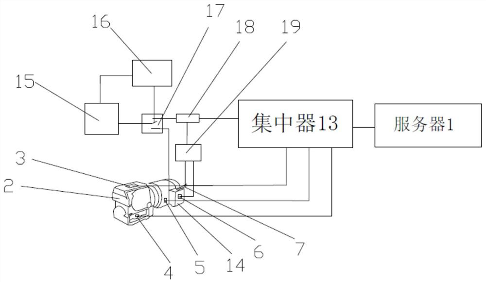
[0038] Embodiment 1: A distributed geared motor energy monitoring system, such as figure 1 As shown, it includes a gear motor 2, a vibration sensor 3, an oil temperature sensor 4, a winding temperature sensor 5, a power supply device 14, a current transformer 6, a voltage probe 7, a server 1, a power supply unit 15, a control module 19, a relay 18, The battery management system 16, the switch 17 and the concentrator 13, the vibration sensor 3 and the winding temperature sensor 5 are all installed on the geared motor 2, the vibration sensor 3 detects the vibration amplitude of the geared motor 2, and the vibration sensor 3 communicates with the concentrator through the wireless communication unit 13 is connected, the oil temperature sensor 4 detects the oil pool temperature of the geared motor 2, the oil temperature sensor 4 is connected to the concentrator 13 through the wireless communication unit, the winding temperature sensor 5 detects the winding temperature of the geared ...


PUM


Abstract

The invention discloses a distributed deceleration motor energy monitoring system and method, comprising a deceleration motor, a collection device, a power supply device, a power supply unit, a concentrator, a working state detection device of the deceleration motor, a relay and a server, and the collection device is installed on the deceleration motor. The acquisition device is used to collect the vibration amplitude, winding temperature and oil pool temperature of the geared motor. The acquisition device is connected to the concentrator. The concentrator is used to centrally process the data collected by the acquisition device and transmit it to the server. The power supply device is used to provide the acquisition device. The power supply unit is connected with the concentrator through the relay, the control end of the relay is connected with the working state detection device of the deceleration motor, and the working state detection device of the deceleration motor is connected with the power supply device. The invention monitors the vibration amplitude, oil pool temperature and winding temperature of the geared motor in real time through the vibration sensor, the oil temperature sensor and the winding temperature sensor, and the monitoring area is wide.

Description

technical field [0001] The invention relates to the field of motor power supply monitoring, in particular to a distributed deceleration motor energy monitoring system and method. Background technique [0002] For an industrial environment where geared motors are distributed in clusters, if energy management is required for each geared motor, multiple current transformers need to be installed in the main control system. The number, cost, and complexity of installation of current transformers form a point of contradiction with the number of equipment for energy management. [0003] The current distributed geared motor monitoring gateway (ie concentrator) mainly has the following shortcomings: [0004] 1. When wired power supply is used, it is difficult to implement cable laying or there is no available power supply; [0005] 2. If the motor power is used directly, when the start and stop are frequent, the gateway power supply is switched off and on alternately, so it is not ...

Claims


Application Information

Patent Timeline
Patent Type & Authority Patents(China)
IPC IPC(8): G01D21/02G08C17/02G01K1/024H02M3/155H02K11/20H02K11/25
CPCG01D21/02G08C17/02G01K1/024H02M3/155H02K11/20H02K11/25
Inventor 陈德木杨晓斌池永为陆建江马文文余小辉
Owner HANGZHOU JIE DRIVE TECH
Why Eureka
Try Eureka