Solder strip feeding device and battery string preparation device

A technology for welding ribbons and battery sheets, which is applied in shearing devices, circuits, photovoltaic power generation, etc., can solve the problems of low battery string preparation efficiency and other problems

Pending Publication Date: 2020-09-15
WUXI LEAD INTELLIGENT EQUIP CO LTD
View PDF0 Cites 8 Cited by
  • Summary
  • Abstract
  • Description
  • Claims
  • Application Information

AI Technical Summary

Problems solved by technology

[0004] The application provides a ribbon feeding device and a battery string preparation device to solve the problem of low efficiency of battery string preparation in the prior art

Method used


Image

  • Solder strip feeding device and battery string preparation device
  • Solder strip feeding device and battery string preparation device
  • Solder strip feeding device and battery string preparation device

Examples


Embodiment 1

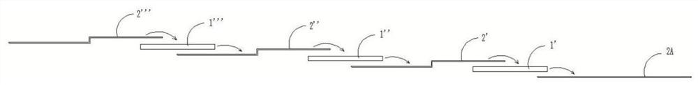
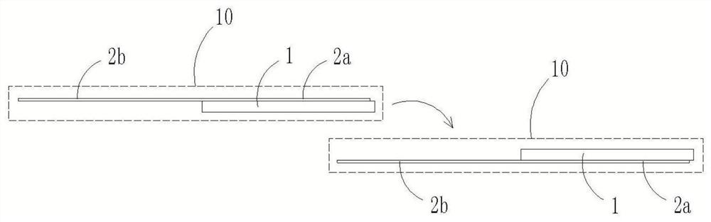
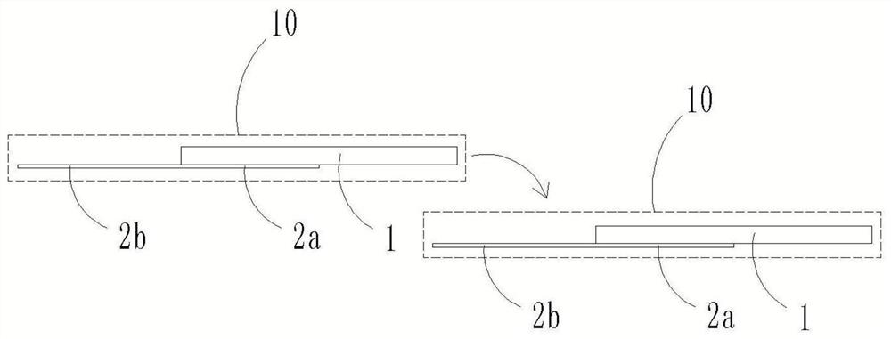
[0070] The ribbon loading device 200 transports the finished ribbon 2 to contact with the battery sheet 1 to construct the stringer unit 10 .

[0071] In this embodiment, the finished ribbon 2 is a ribbon material segment that meets the technical requirements and can be directly used to construct the stringer unit 10 .

[0072] When multiple welding ribbons 2 need to be laid on one battery sheet 1 , the welding ribbon feeding device 200 can move each welding ribbon 2 one by one to contact the battery sheet 1 . Alternatively, the ribbon feeding device 200 can transport multiple ribbons 2 to contact the battery sheet 1 at the same time.

[0073] Wherein, the ribbon feeding device 200 includes a ribbon extractor (not shown) and a ribbon extractor (not shown); Driving components such as linear modules and robots; after the ribbon extractor is extracted to the finished ribbon 2, the ribbon extractor drives the ribbon extractor to move towards the construction station of the string...

Embodiment 2

[0075] In order to facilitate the continuous operation of the equipment, the ribbon feeding device 200 can prepare the finished ribbon 2 and then transport the finished ribbon 2 to the construction station of the stringer unit 10 .

[0076] In one embodiment, the ribbon loading device 200 includes: a ribbon unwinding mechanism 210 for releasing the ribbon material; a ribbon cutting mechanism 220 located downstream of the ribbon unwinding mechanism 210 and capable of cutting the ribbon material Ribbon; the ribbon pulling mechanism 230 can pull out the ribbon material strip from the ribbon unwinding mechanism 210, and pull the ribbon material ribbon through the ribbon cutting mechanism 220 so that the ribbon cutting mechanism 220 can cut the ribbon material bring.

[0077] refer to Figure 11 , The ribbon unwinding mechanism 210 includes an unwinding shaft 211 and an unwinding driver that drives the unwinding shaft 211 to rotate; The unwinding shaft 211 rotates to release the ...

Embodiment 3

[0083] The battery string preparation device is provided with multiple sets of welding ribbon feeding devices 200 described in Embodiment 2, which are respectively used to prepare a set of welding ribbons 2 .

[0084] Alternatively, the battery string preparation device is provided with only one set of welding ribbon feeding device 200 described in Embodiment 2, and multiple sets of welding ribbons 2 are prepared one by one through the welding ribbon feeding device 200 .


PUM


Abstract

The invention discloses a solder strip feeding device which comprises a solder strip unwinding mechanism, a solder strip cutting mechanism and a solder strip traction mechanism. The multiple sets of welding strip cutting mechanisms are arranged at intervals in the linear direction. A welding strip material strip unwound by the welding strip unwinding mechanism is dragged by the welding strip traction mechanism and sequentially penetrates through all the welding strip cutting mechanisms. The solder strip cutting mechanism cuts off the material strips, and multiple sets of solder strips can be obtained. Therefore, the solder strip feeding device can supply multiple sets of material strips at a time, and the preparation efficiency of the battery string is improved. The solder strip feeding device further comprises a solder strip lifting mechanism capable of driving the solder strip cutting mechanism to be close to or away from the material strip so as to facilitate strip conveying or cutting of the material strip. The invention further discloses a battery string preparation device which comprises the solder strip feeding device, a battery piece feeding device and a lamination device.The lamination device can receive the series welding units composed of the battery pieces and the welding strips and can also achieve lamination of the series welding units, and then the battery string can be conveniently prepared.

Description

technical field [0001] The present application relates to the technical field of photovoltaic equipment, in particular to a ribbon feeding device and a battery string preparation device. Background technique [0002] When preparing battery strings by traditional methods, refer to figure 1 , usually laying a battery piece 1' first, then laying a welding ribbon 2' on the battery piece 1', and making the second end of the welding ribbon 2' fall behind the battery piece 1'; then laying a battery piece 1 ", and make the battery sheet 1" cover the second end of the laid ribbon 2', and then lay the ribbon 2" on the battery sheet 1", similarly, the second end of the ribbon 2" falls to the battery sheet 1” behind; then, lay the battery piece 1”’ on the second end of the welding strip 2”, and lay the welding strip 2”’ on the battery piece 1”’… In this way, one battery piece and one welding strip are laid successively. Finally, a battery string is formed. In addition, in traditional...

Claims


Application Information

Patent Timeline
Patent Type & Authority Applications(China)
IPC IPC(8): H01L31/18H01L31/05B65H16/00B23D15/02
CPCB23D15/02B65H16/00H01L31/0504H01L31/188Y02E10/50Y02P70/50
Inventor 不公告发明人
Owner WUXI LEAD INTELLIGENT EQUIP CO LTD
Why Eureka
Try Eureka