
A cylindrical battery sealing steel ball fixture tray mechanism

A technology for cylindrical batteries and fixture trays, which is applied to battery pack parts, electrolyte battery manufacturing, non-aqueous electrolyte batteries, etc. It can solve the problems of no positioning function and difficult simultaneous attitude adjustment of multiple batteries, and meet the requirements of loading scalability needs, meet the needs of posture adjustment, and achieve obvious effects

Active Publication Date: 2022-03-11
HEFEI GUOXUAN HIGH TECH POWER ENERGY
View PDF12 Cites 1 Cited by
  • Summary
  • Abstract
  • Description
  • Claims
  • Application Information

AI Technical Summary

Problems solved by technology

However, the fixture tray in practical applications only meets the clamping of a single unit, and generally does not have a positioning function, and it is even more difficult to adjust the posture of multiple batteries at the same time

Method used


Image

  • A cylindrical battery sealing steel ball fixture tray mechanism
  • A cylindrical battery sealing steel ball fixture tray mechanism
  • A cylindrical battery sealing steel ball fixture tray mechanism

Examples


Embodiment 1

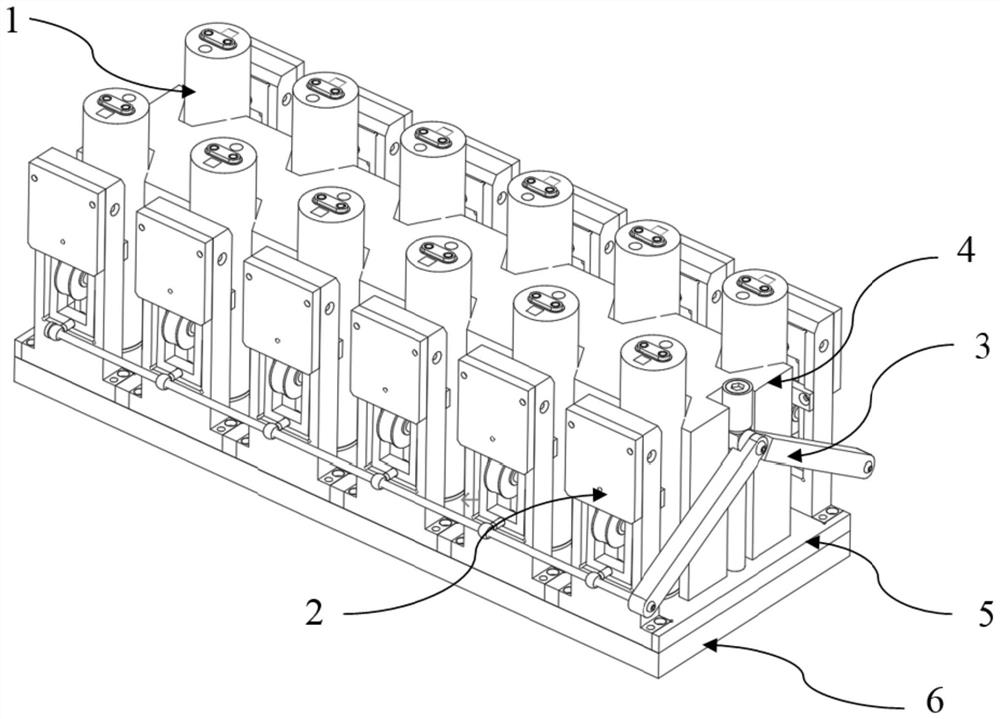
[0030] Example 1, see figure 1 , a cylindrical battery sealing ball fixture tray mechanism, including a bottom plate, the bottom plate includes a first bottom plate 5 above and a second bottom plate 6 below, the first bottom plate 5 is made of PE material, and is fixedly connected with the second bottom plate 6 .

[0031] A base block 4 is fixed on the bottom plate, and at least one first notch 27 for accommodating the cylindrical battery 1 is provided longitudinally on the lateral side of the base block 4, and a frame body 7 fixed on the bottom plate is provided outside the first notch 27 The first baffle plate 11 is fixed on the laterally outer surface of the frame body 7, and the inside of the frame body 7 is movably connected with a laterally rotating side clip assembly 2, and a first elastic spring is connected between the side clip assembly 2 and the first baffle plate 11. Part 13.

[0032] In this embodiment, one of the lateral sides of the base block 4 ( figure 1 A f...

Embodiment 2

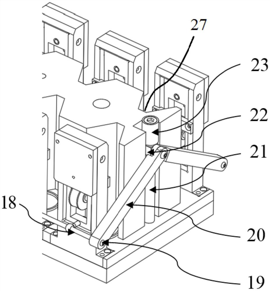
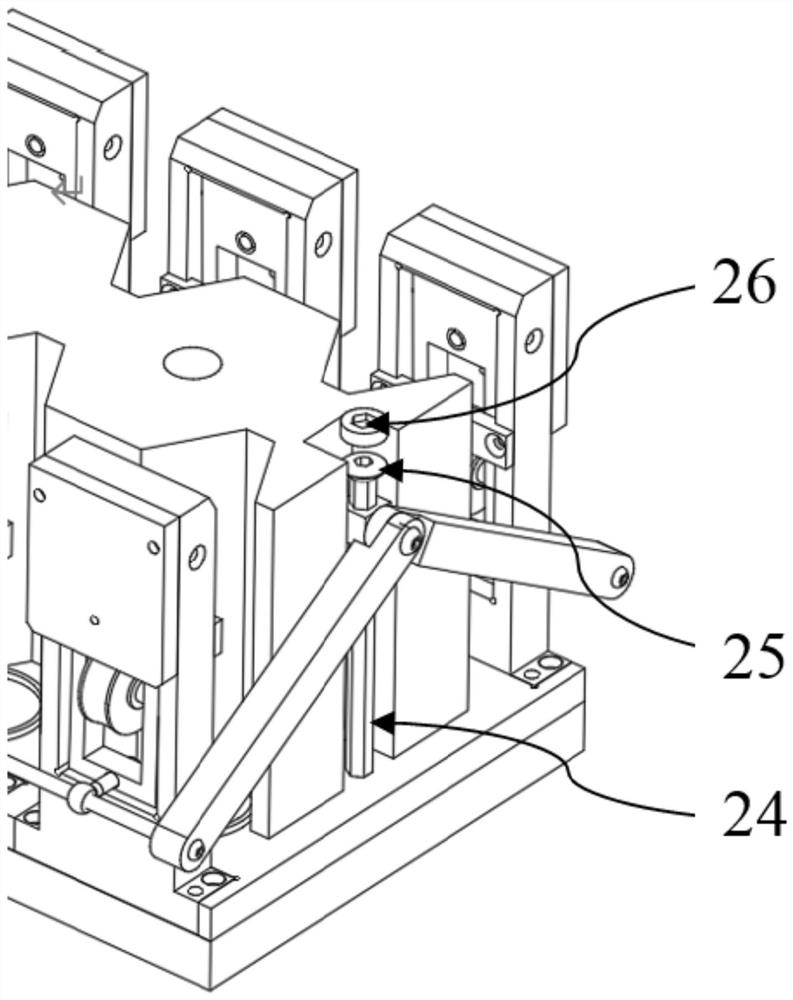
[0038] Example 2, such as Figure 2-3 As shown, further, a column 24 is also fixed on the bottom plate, and the top of the column 24 is movably connected with an adjustment assembly along the height direction, and the adjustment assembly and the side clamp assembly 2 are connected through a linkage assembly 3, and the linkage assembly 3 includes that when the adjustment assembly descends, The side clamp assembly 2 rotates laterally outward to release the first state of the cylindrical battery 1 , and when the adjustment assembly rises, the side clamp assembly 2 rotates inward to press the cylindrical battery 1 in the second state.

[0039] Preferably, the column 24 is arranged on one side of the longitudinal surface of the base block 4 ( figure 1 What is shown is the front side of the base block 4, and it can also be arranged on the rear side of the base block 4), so as to facilitate the common connection of the linkage assembly 3, the adjustment assembly, and the side clamp a...


PUM


Abstract

The invention discloses a cylindrical battery sealing steel ball fixture tray mechanism in the field of cylindrical battery liquid injection, which includes a bottom plate, a base block is fixed on the bottom plate, and at least one first groove for accommodating cylindrical batteries is longitudinally opened on the lateral side of the base block The outer side of the first notch is provided with a frame body fixed on the bottom plate; the first baffle plate is fixed on the lateral outer surface of the frame body, and the inside of the frame body is movably connected with a laterally rotating side clamp assembly, and the side clamp assembly and A first elastic component is connected between the first baffles. The present invention can realize fast clamping of the cylindrical battery through the side clamp assembly, and can quickly meet the posture adjustment requirements of the cylindrical battery through the adjustment assembly and the linkage assembly, and when the first notch on the side of the base block is greater than or equal to two, it can be used The mode of independent cylindrical battery cells and multi-position linkage meets the needs of loading scalability. The implementation effect of the present invention is obvious, can practically and effectively meet various demand indexes, has outstanding substantive characteristics and remarkable progress.

Description

technical field [0001] The invention relates to the field of cylindrical battery liquid injection, in particular to a cylindrical battery sealing steel ball fixture tray mechanism. Background technique [0002] In the production of power lithium batteries, liquid injection is an essential process; the sealing quality of the liquid injection hole after liquid injection is related to the safety of the battery and the service life of the product, which cannot be ignored. [0003] At present, the method of sealing the liquid injection hole is to weld the sealing sheet or the sealing steel ball. The liquid injection hole of the cylindrical battery is located on the axial surface of the top, and the space is small, so it is not suitable for welding the sealing sheet; and because the price range of the sealing steel ball equipment is low, The price of sealing aluminum sheets and sealing nails is higher than that of steel balls; currently, cylindrical batteries generally adopt the o...

Claims


Application Information

Patent Timeline
Patent Type & Authority Patents(China)
IPC IPC(8): H01M50/636H01M10/058
CPCH01M10/058Y02E60/10Y02P70/50
Inventor 郭彪程辉
Owner HEFEI GUOXUAN HIGH TECH POWER ENERGY
Learn More