
Lens module and electronic device

A lens module and electronic device technology, applied in electromechanical devices, focusing devices, projection devices, etc., can solve the problem of reducing the contact area between the voice coil motor and the bearing seat, reducing the safety factor of glue bonding strength, voice coil motor and Problems such as the easy separation of the bearing seat can reduce the risk of separation, improve reliability and yield, and meet the thrust requirements.

Active Publication Date: 2022-04-05
TRIPLE WIN TECHSHENZHEN CO LTD
View PDF11 Cites 0 Cited by
  • Summary
  • Abstract
  • Description
  • Claims
  • Application Information

AI Technical Summary

Problems solved by technology

Among them, the voice coil motor and the bearing seat are usually mainly bonded by glue, but due to the material of the glue and the bonding area, the bonding strength is not enough, which often leads to the separation of the voice coil motor and the bearing seat. Generally, in order to reduce the size of the product, the height of the lens module is usually chosen to be lowered. At the same time, in order to prevent glue overflow, the glue overflow storage space is usually involved. There is a storage space for glue overflow on the edge, which will further reduce the glue contact area between the voice coil motor and the bearing seat, thereby reducing the safety factor of glue bonding strength, and making the voice coil motor and the bearing seat easy to separate
In addition, in order to improve the bonding strength between the voice coil motor and the bearing seat, it is necessary to use colloid with high bonding strength and high bonding safety factor, which will increase the cost

Method used


Image

  • Lens module and electronic device
  • Lens module and electronic device
  • Lens module and electronic device

Examples


Embodiment Construction

[0032] In order to better understand the above objects, features and advantages of the present invention, the present invention will be described in detail below in conjunction with the accompanying drawings and specific embodiments. It should be noted that, in the case of no conflict, the embodiments of the present application and the features in the embodiments can be combined with each other. In the following description, a lot of specific details are set forth to facilitate a full understanding of the present invention, and the described embodiments are only some of the embodiments of the present invention, but not all of them. Based on the implementation manners in the present invention, all other implementation manners obtained by persons of ordinary skill in the art without making creative efforts belong to the scope of protection of the present invention.

[0033] Unless otherwise defined, all technical and scientific terms used herein have the same meaning as commonly...


PUM


Abstract

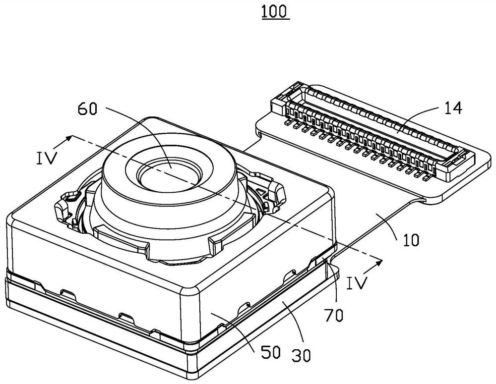
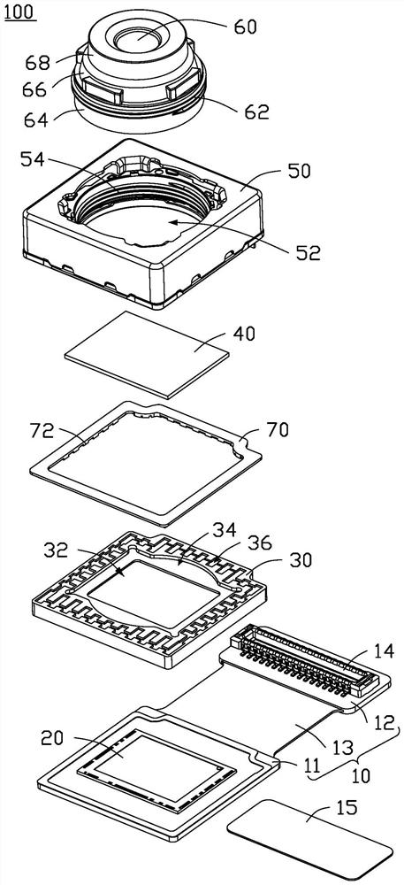
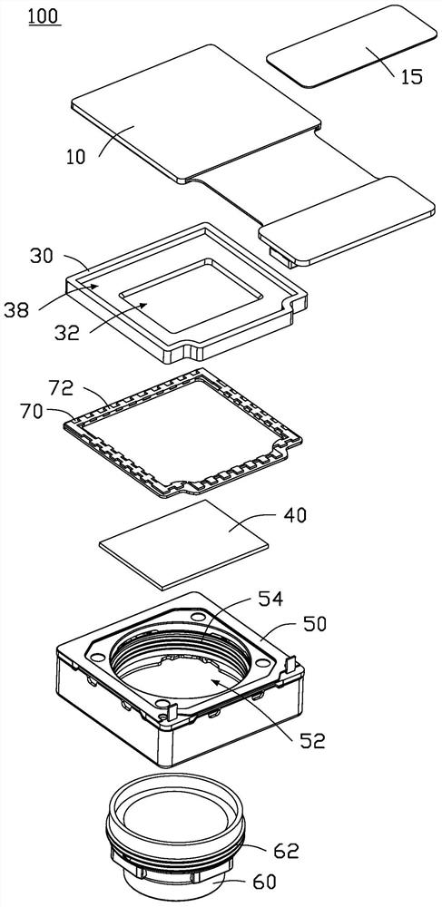
A lens module, comprising a voice coil motor, a bearing seat, and colloid connecting the voice coil motor and the bearing seat, grooves are arranged on the side walls of the bearing seat, and the grooves are filled with the colloid, The colloid has a cube shape with a protruding part, and the protruding part is engaged with the bearing seat. The invention also provides an electronic device using the lens module.

Description

technical field [0001] The invention relates to the field of electronics and optical devices, in particular to a lens module and an electronic device. Background technique [0002] Most lens modules are composed of six parts: lens, glass filter, carrier, voice coil motor, photosensitive chip and circuit board. Among them, the voice coil motor and the bearing seat are usually mainly bonded by glue, but due to the material of the glue and the bonding area, the bonding strength is not enough, which often leads to the separation of the voice coil motor and the bearing seat. Generally, in order to reduce the size of the product, the height of the lens module is usually chosen to be lowered. At the same time, in order to prevent glue overflow, the glue overflow storage space is usually involved. There is a storage space for glue overflow on the edge, which will further reduce the glue contact area between the voice coil motor and the bearing seat, thereby reducing the safety fact...

Claims


Application Information

Patent Timeline
Patent Type & Authority Patents(China)
IPC IPC(8): H04N5/225H04M1/02
CPCH04M1/0264H04N23/50H04N23/57H04N23/55H04N23/54H02K41/0356G02B7/08G02B7/022G02B13/0025G03B17/02G03B13/36G02B7/09G03B2205/0069G03B21/145G03B30/00
Inventor 陈信文李静伟丁盛杰李明
Owner TRIPLE WIN TECHSHENZHEN CO LTD
Learn More