Rotating mechanism

A technology of a rotating mechanism and a driving mechanism, which is applied in the field of aircraft, and can solve the problems that the rotating and folding mechanism is difficult to maintain a stable and reliable unfolded or folded state, the aircraft is damaged, and it is difficult to ensure flight stability. It is easy to process and realize, and guarantees stability. and the effect of safety and simple structure

Active Publication Date: 2020-09-18
成都纵横大鹏无人机科技有限公司
View PDF7 Cites 0 Cited by
  • Summary
  • Abstract
  • Description
  • Claims
  • Application Information

AI Technical Summary

Problems solved by technology

[0003] The technical problem to be solved and the technical task proposed by the present invention are to improve the existing technology and provide a rotating mechanism to solve the problem that the rotating and folding mechanism in the current technology is difficult to maintain a stable and reliable unfolded state or folded state, so that it is difficult to ensure the flight time of the flight. The stability of the aircraft is prone to the problem of damage to the aircraft

Method used


Image

  • Rotating mechanism
  • Rotating mechanism
  • Rotating mechanism

Examples


Embodiment 1

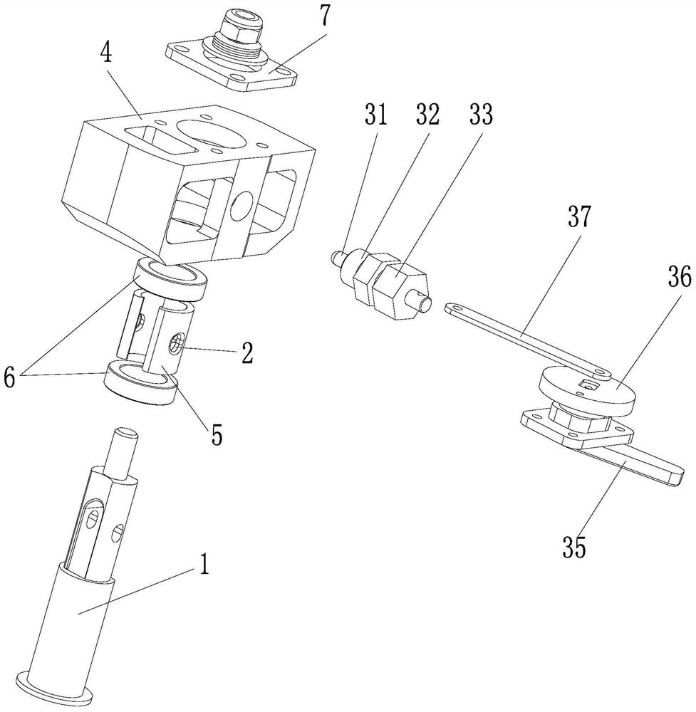
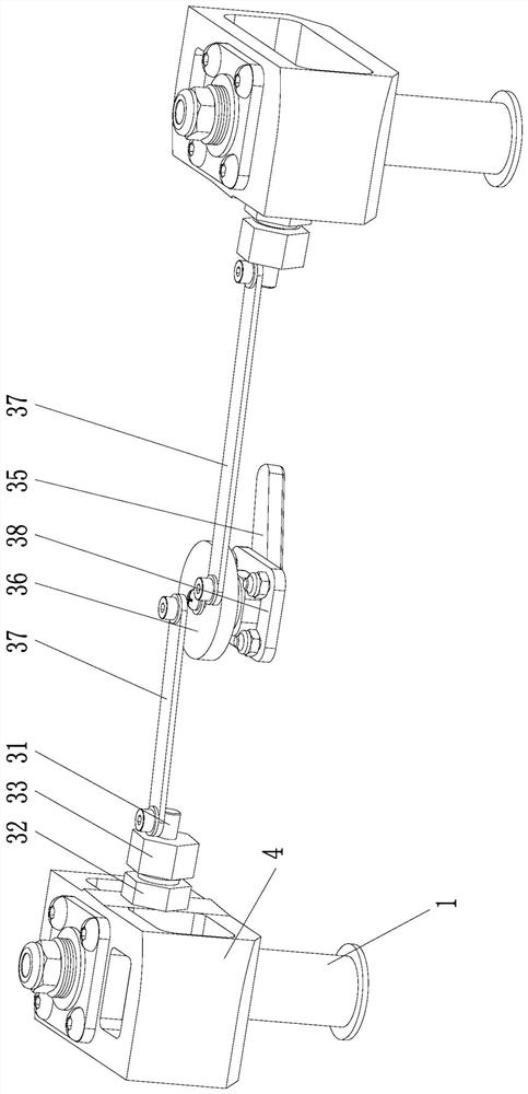
[0025] Such as Figure 1 to Figure 4 As shown, a rotating mechanism mainly includes a rotating shaft 1, a locking part 2 and a locking pin assembly 3, wherein the rotating shaft 1 is fixedly connected to the first pivoting part and is rotatably connected to the second pivoting part, and the locking part 2 is The holes distributed along the circumference of the rotating shaft 1, and the axial direction of the holes are along the radial direction of the rotating shaft 1, the lock pin assembly 3 can move between the locking position and the unlocking position, and the locking pin assembly 3 can be arranged in the waiting position If the pivoting part is on the first part, the locking part 2 is arranged on the second part to be pivoting, or if the lock pin assembly 3 is arranged on the second part to be pivoting, then the locking part 2 is arranged on the first part to be pivoting and / or the shaft 1 , so that relative rotation can be carried out between the first pivoting member a...

Embodiment 2

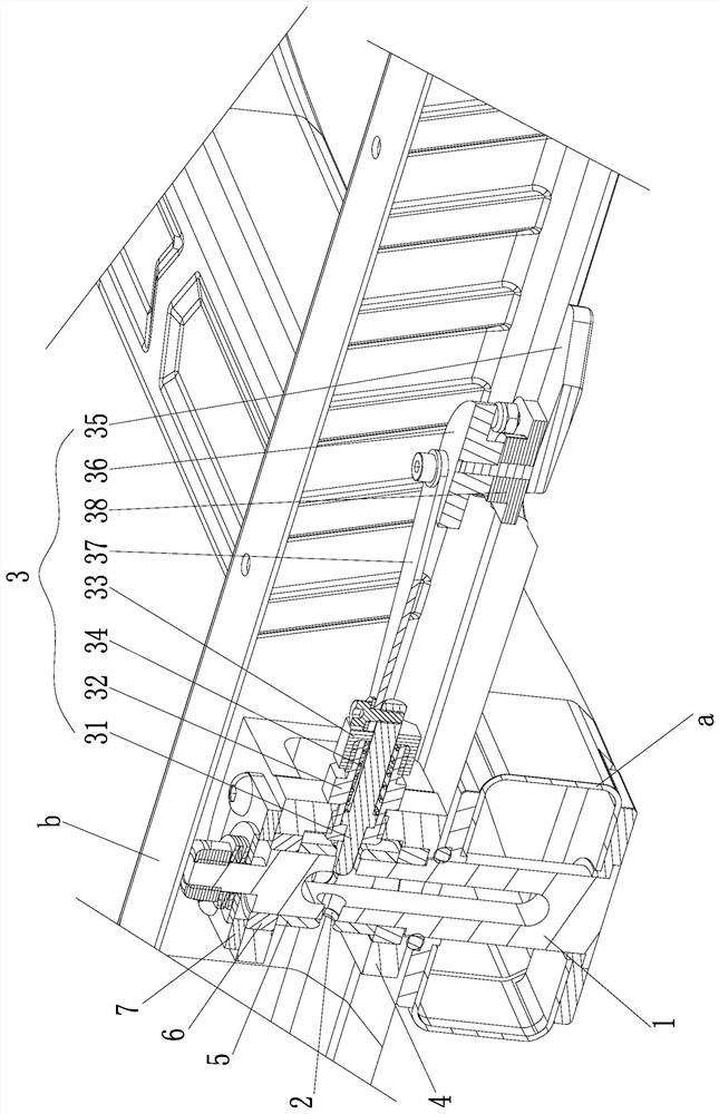
[0036] Such as Figure 5 In the rotating mechanism shown, the rotating shaft 1 is fixedly connected to the main arm b, and the rotating shaft 1 is rotationally connected to the folding arm a. The locking part 2 is a hole arranged on the folding arm a along the circumferential direction of the rotating shaft 1, and the hole The axial direction of is along the axial direction of rotating shaft 1;

[0037] The lock pin assembly 3 mainly includes a lock pin 31 and a lock pin seat 32. The lock pin seat 32 is cylindrical, and the lock pin 31 is inserted on the cylindrical lock pin seat 32 and slides along it to move between the locked position and the unlocked position. Specifically, the axial direction of the locking pin seat 32 is along the axial direction of the rotating shaft 1. When the main arm b and the folding arm a are relatively rotated in place, the locking pin 31 of the locking pin assembly 3 is inserted into the hole so that the main arm b is in the The folding arm a i...


PUM


Abstract

The invention discloses a rotating mechanism. The rotating mechanism includes a rotating shaft which is used for being fixedly connected with one of a to-be-pivoted piece I and a to-be-pivoted piece II and is rotationally connected with the other one of the to-be-pivoted piece I and the to-be-pivoted piece II; a locking part which is distributed in the circumferential direction of the rotating shaft; a lock pin assembly moving between a locking position and an unlocking position; a locking portion being arranged on one of the first piece to be pivoted and the second piece to be pivoted, the lock pin assembly being arranged on the other one of the first piece to be pivoted and the second piece to be pivoted, wherein the lock pin assembly is matched with the locking portion when switched tothe locking position so as to forbid relative rotation of the first piece to be pivoted and the second piece to be pivoted. The rotating mechanism can reliably lock the rotating state, keep the aircraft in the unfolding state and the folding state stably, effectively prevent the aircraft from shifting in the state, and can be automatically locked when rotating in place, so that the flight stability and safety are guaranteed, and the stability of the folding state is guaranteed.

Description

technical field [0001] The invention relates to the technical field of aircraft, in particular to a rotating mechanism. Background technique [0002] UAV is an unmanned aircraft controlled by radio remote control equipment and self-contained program control device. Industrial-grade multi-rotor UAV is widely used, with small and light size, intelligent control, and flexible carrying of various mission equipment, etc. It is used in urban building surveying and mapping, emergency response, monitoring and power inspection and other application scenarios. UAVs usually adopt a rotating and folding structure. When flying, the arms of the aircraft are unfolded, and when storage and transportation are required The arms of the aircraft are folded and folded to reduce the occupied space, facilitate storage, improve space utilization, and reduce transportation costs. However, the rotation and folding mechanism of aircraft commonly used at present is usually difficult to maintain a stab...

Claims


Application Information

Patent Timeline
IPC IPC(8): B64C1/06B64C1/30
CPCB64C1/063B64C1/30
Inventor 李季王利光
Owner 成都纵横大鹏无人机科技有限公司
Why Eureka
Try Eureka