Eureka AIR delivers breakthrough ideas for toughest innovation challenges, trusted by R&D personnel around the world.

Automatic cyclic detection device for broken yarn and control method

A technology of roving detection and control methods, applied in textiles and papermaking, etc., can solve the problems of workers' visual fatigue, affecting workers' vision, and high detection intensity

Active Publication Date: 2020-09-18
微山县微山湖微电子产业研究院有限公司
View PDF8 Cites 1 Cited by
  • Summary
  • Abstract
  • Description
  • Claims
  • Application Information

AI Technical Summary

Problems solved by technology

In order to find yarn breakage and other situations in the production process in time and deal with them in a timely manner, workers usually detect through visual inspection. This detection method is easy to cause missed detection, and the detection intensity is high, which leads to visual fatigue of workers. Long-term work will affect workers' vision

Method used


Image

  • Automatic cyclic detection device for broken yarn and control method
  • Automatic cyclic detection device for broken yarn and control method
  • Automatic cyclic detection device for broken yarn and control method

Examples


Embodiment

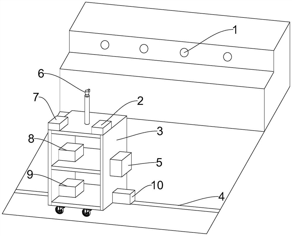
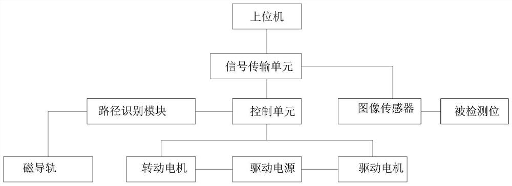
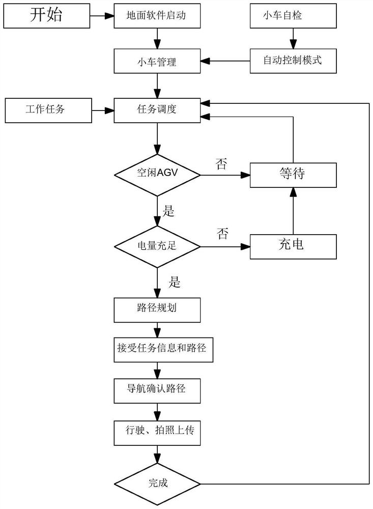
[0042] Please refer to figure 1 , figure 1 Shown is a schematic structural diagram of an embodiment of the present invention. This embodiment provides an automatic yarn breakage roving detection device and a control method, wherein the automatic yarn breakage roving detection device includes a moving component, a sensing component, a signal transmission unit 7, a route Identify the track, control unit 2 and host computer. Wherein, the moving component serves as a carrier of the sensing component and the control unit 2 and can drive the sensing component and the control unit 2 to move. The control unit 2 is used to control the image sensor 6 to perform image acquisition, and at the same time control the moving component to move on the route identification track. The sensing component includes an image sensor 6 , which is arranged on the moving component, and the image sensor 6 can collect image characteristic information of the detected position, and transmit the collected in...


PUM


Abstract

The invention provides an automatic cyclic detection device for broken yarn and a control method, and relates to the technical field of textiles. The automatic cyclic detection device for the broken yarn comprises a moving assembly, a sensing assembly, a signal transmission unit, a route recognition rail, a control unit and an upper computer. The sensing assembly comprises an image sensor, and theimage sensor is arranged on the moving assembly. The signal transmission unit is arranged on the moving assembly and can achieve information exchange among the upper computer, the control unit and the image sensor. The control unit is used for controlling the moving assembly to move and stay on the route recognition rail. The device replaces manual inspection, the broken yarn can be found in timeand reported to a broken yarn station, a worker is prompted to handle the broken yarn immediately, and one worker can watch over and handle multiple yarn winding machines. In addition, the inventionfurther provides a control method of the automatic circulating detection device for the broken yarn, and the control method is used for controlling the automatic circulating detection device for the broken yarn, so that the automatic cyclic detection device for the broken yarn efficiently and orderly carries out broken yarn inspection work.

Description

technical field [0001] The invention relates to the technical field of textiles, in particular to an automatic yarn break circuit detection device and a control method. Background technique [0002] In the preparation stage of warp beams used in machines such as textile machines, yarns are pulled out all at once from a plurality of yarn suppliers installed in creel devices, and are wound onto warp beams by a winding device or the like. Even if one of the yarns pulled out from the creel device is broken, the number of yarns wound on the warp beam will be insufficient, so it is necessary to detect yarn breakage for all the yarns in the winding process. In addition, when a yarn breakage occurs, a worker wants to be able to identify which yarn supply body the yarn breakage has occurred in order to repair the yarn breakage. At present, the detection of yarn breakage in the yarn-making industry is basically two methods: manual inspection and photoelectric detection. The former re...

Claims


Application Information

Patent Timeline
IPC IPC(8): D01H13/14D01H13/16
CPCD01H13/145D01H13/1633
Inventor 丁滨许子科洪汀荃周赛琲杨春孟苗雨露赵文通
Owner 微山县微山湖微电子产业研究院有限公司
Why Eureka
Eureka Blog
Learn More