
Shower waste water collecting device

A waste water collection and water collection technology, which is applied in water supply devices, indoor sanitary piping devices, grease/oily substance/float removal devices, etc., can solve the problem of the large volume of ordinary waste water collectors, unsightly installation, and waste water collection and reuse. Low efficiency and other problems, to achieve the effect of not easy to breed bacteria, improve the overall aesthetics, and improve the efficiency of waste heat reuse

Pending Publication Date: 2020-09-18
甘秀坚
View PDF0 Cites 2 Cited by
  • Summary
  • Abstract
  • Description
  • Claims
  • Application Information

AI Technical Summary

Problems solved by technology

[0003] In order to solve the above problems, the present invention provides a shower wastewater collection device, which is smaller than the technology in the patent No. 2015101776616 of "A non-slip floor mat that can recycle shower wastewater" invented by myself, and it is plugged in the original floor drain. Simple, versatile and highly interchangeable, it is used in hot water systems with shower waste water recycling and reuse, replacing its waste water collector, without changing the bathroom decoration and the original water channel, the shower waste water can be collected and reused conveniently , Solve the problem of large volume of ordinary waste water collector, unsightly installation, and low efficiency of waste water collection and reuse

Method used


Image

  • Shower waste water collecting device
  • Shower waste water collecting device
  • Shower waste water collecting device

Examples


Embodiment Construction

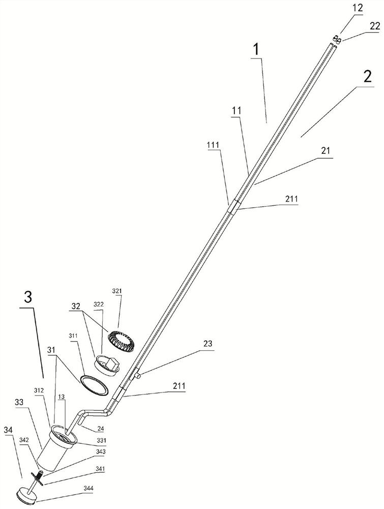
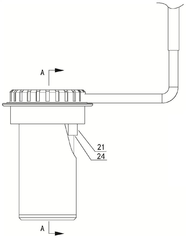
[0033] Such as figure 1 figure 2 , image 3 , Figure 4 , Figure 5 , Image 6 , Figure 7 , Figure 8 Shown is a specific implementation example of the present invention. A shower wastewater collection device, comprising: a water suction pipe 1, a drain pipe 2, and a water collecting floor drain plug 3. The water suction pipe 1 is provided with a water suction pipe 11, and the water suction pipe 11 extends into the water collecting floor drain plug 3, and the drain pipe 2 is provided with a drainage pipe 21, and the drainage pipe 21 extends outside the water collecting floor drain plug 3, and the water collecting floor drain plug 3 is opened at the top of the shell A hair filter 32 is installed inside, and the water-collecting floor drain plug 3 is provided with a water-sealing structure 31 .

[0034] The water sealing structure 31 includes an interchangeable water sealing part 311 and a water sealing edge 312. The water sealing edge 312 is a circle edge of the outer...


PUM


Abstract

The invention discloses a shower waste water collecting device. The shower waste water collecting device comprises a water suction pipe, a water discharge pipe and a water collecting floor drain plug,wherein the water suction pipe is provided with a water suction port, the water suction port extends into the water collecting floor drain plug, the water discharge pipe is provided with a water discharge port, the water discharge port extends out of the water collecting floor drain plug, the water collecting floor drain plug is provided with a water sealing structure, the water sealing structurecomprises an interchangeable water sealing piece, the water suction pipe comprises a water suction pipeline and a water suction pipe connecting port, the water discharge pipe comprises a water discharge pipeline, a water discharge connecting port and a throttling three-way valve, and the water collection floor drain plug comprise a hair filter, a sewage draining device and a cleaning device. Theshower waste water collecting device is small in size, is plugged in an original floor drain, is simple and convenient to install, is high in universal interchangeability, is applied to a hot water system with a shower waste water recycling function, replaces a waste water collector of the hot water system, can conveniently collect and recycle shower waste water without the need for changing bathroom decoration and original waterway channels, and solves the problems that a common waste water collector is large in size, unsightly in installation and low in waste water collecting and recycling efficiency.

Description

technical field [0001] The invention relates to a shower wastewater collection device. Background technique [0002] The technology in the patent No. 2015101776616 of "A non-slip floor mat that can recycle shower wastewater" invented by me has greatly reduced the volume compared to the old coil-type shower waste heat recovery tray, but the anti-slip floor mat is still used as a The drip tray collects waste water. In order to obtain water storage space in the actual use process, this type of waste water collector must have a certain height above the floor of the bathroom, so it has the disadvantages of large volume, large bathroom space, unsightly installation, and high production and transportation costs. . Contents of the invention [0003] In order to solve the above problems, the present invention provides a shower wastewater collection device, which is smaller than the technology in the patent No. 2015101776616 of "A non-slip floor mat that can recycle shower wastewa...

Claims


Application Information

Patent Timeline
IPC IPC(8): E03C1/12E03C1/122E03F5/04E03F5/06E03F5/14
CPCE03C1/12E03C1/122E03C2001/005E03F5/0408E03F5/041E03F5/06E03F5/14
Inventor 甘秀坚
Owner 甘秀坚
Learn More