Compound elastic cantilever type gas turbine supporting ring vibration reduction and impact-resistance assembly

A gas turbine and elastic cantilever technology, applied in gas turbine devices, engine components, mechanical equipment, etc., can solve problems such as harsh environmental requirements and out-of-control manipulation

Pending Publication Date: 2020-09-18
中国船舶重工集团公司第七0三研究所
View PDF0 Cites 0 Cited by
  • Summary
  • Abstract
  • Description
  • Claims
  • Application Information

AI Technical Summary

Problems solved by technology

At the same time, with the extensive equipment of advanced shipboard instruments such as electronic countermeasures and communication and navigation,

Method used


Image

  • Compound elastic cantilever type gas turbine supporting ring vibration reduction and impact-resistance assembly
  • Compound elastic cantilever type gas turbine supporting ring vibration reduction and impact-resistance assembly

Examples


specific Embodiment approach 1

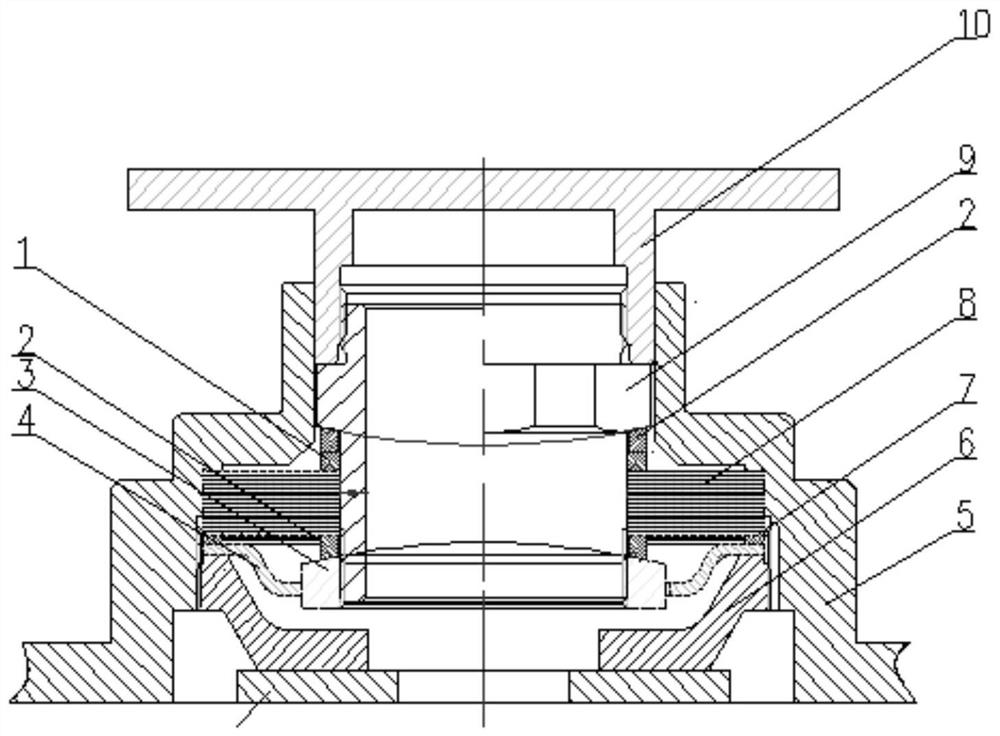
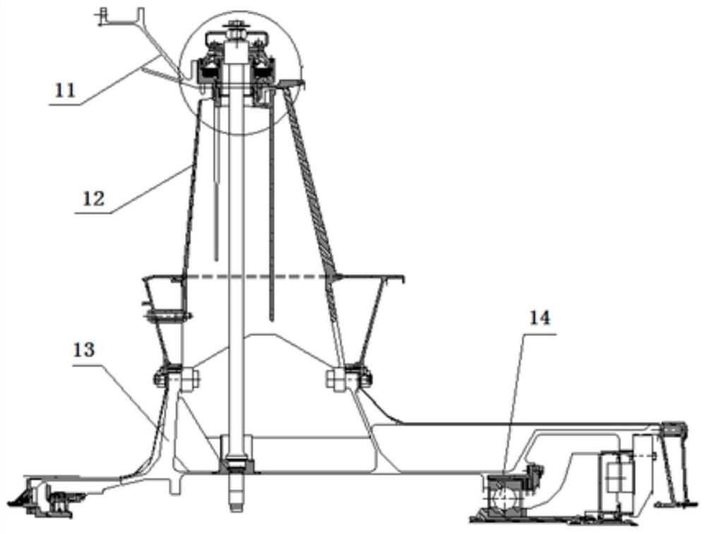
[0015] Embodiment 1: Combining Figure 1-Figure 2 Illustrating this embodiment, the composite elastic cantilever gas turbine turbine support ring vibration damping and anti-shock assembly described in this embodiment includes an adjusting ring 1, a spherical bushing 2, a nut 3, a compression member 4, a compensator housing 5, and a nut. 6. A set of annular thin plates 8, pipe connection rings 9 and guide struts 10; the pipe connection ring 9 is installed in the compensator housing 5, the spherical shaft sleeve 2, the adjustment ring 1, a group of annular thin plates 8 and nuts 3 are sleeved On the outer side wall of the pipe adapter ring 9, and the nut 3 is screwed with the pipe adapter ring 9, the inner ring of the compression member 4 is sleeved on the nut 3, the nut 6 is installed on the inner side wall of the compensator housing 5, and the compression member 4 The outer ring is located between the nut 6 and a set of annular thin plates 8 , and the guide strut 10 is install...

specific Embodiment approach 2

[0016] Specific implementation mode 2: Combining Figure 1-Figure 2 Illustrating this embodiment, the composite elastic cantilevered gas turbine turbine support ring vibration damping and anti-shock assembly in this embodiment, a group of annular thin plates 8 is composed of a plurality of annular thin plates 8 combined and superimposed, and the others are the same as the first embodiment.

specific Embodiment approach 3

[0017] Specific implementation three: combination Figure 1-Figure 2 Illustrating this embodiment, the composite elastic cantilevered gas turbine turbine support ring vibration and shock assembly described in this embodiment further includes a pressure bearing ring 7 installed between the compression member 4 and a set of annular thin plates 8 . The bearing ring acts to support the outer ring of a group of annular thin plates 8 , and clamps the outer ring of the elastic thin plate between the compression member 4 and a group of annular thin plates 8 .


PUM


Abstract

The invention provides a compound elastic cantilever type gas turbine supporting ring vibration reduction and impact-resistance assembly, and relates to a compound elastic cantilever type vibration reduction and impact-resistance assembly device. The purpose of the assembly is to provide a vibration reduction assembly in a turbine supporting ring structure assembly to achieve the function of vibration reduction and meanwhile require good impact-resistance performance so that a turbine rotor is effectively protected and the transmission of rotor vibration excitation is separated. The radial deformation of rotor supporting is controlled, the dynamic and static clearance is small, and the impact and rubbing of turbine rotor blades are prevented. The assembly includes an adjusting ring, a spherical shaft sleeve, a nut, a compression part, a compensator shell body, a screw cap, a group of ring-shaped thin plate, a pipe connecting ring and a guide supporting column. The spherical shaft sleeve, the adjusting ring, the ring-shaped thin plate and the nut are arranged on the outer side wall of the pipe connecting ring in a sleeving mode, the nut is sleeved with an inner ring of the compression part, the screw cap is arranged on the inner side wall of the compensator shell body, an outer ring of the compression part is located between the screw cap and the ring-shaped thin plate, and theguide supporting column is arranged between the compensator shell body and the pipe connecting ring. The assembly is applied to the field of shock resistance and buffering.

Description

technical field [0001] The invention relates to a composite elastic cantilever type vibration damping and anti-shock component device, in particular to a composite elastic cantilever type gas turbine turbine support ring vibration damping and anti-shock component, which is used to realize vibration transmission isolation and impact resistance protection of a gas turbine power turbine rotor system. Background technique [0002] In recent years, with the development of science and technology, the explosive yield and impact duration have increased significantly. The precise calculation mechanism has led to a greatly improved hit rate, and the threat to the ship's electromechanical equipment has become more and more serious. At the same time, with a large number of advanced shipborne instruments such as electronic countermeasures, communication and navigation, the requirements for the environment are more stringent, and a slight shock wave input will lead to a long-term loss of c...

Claims


Application Information

Patent Timeline
IPC IPC(8): F02C7/00F02C6/20F01D25/28F01D25/04
CPCF01D25/04F01D25/28F02C6/203F02C7/00
Inventor 邱中辉郁顺旺何建元梁晨孙彦博季晨孙景国刘洪达张馨周克佳
Owner 中国船舶重工集团公司第七0三研究所
Why Eureka
Try Eureka