

Ignition device for prolonging service cycle of oil-fired boiler
A technology of ignition device and oil-fired boiler, which is applied in the field of ignition device and improves the life cycle of oil-fired boilers. It can solve the problems of short life cycle of oil-fired boilers, reduce maintenance workload, avoid electrode damage, and facilitate maintenance.
- Summary
- Abstract
- Description
- Claims
- Application Information
AI Technical Summary
Problems solved by technology
Method used
Image

Examples
specific Embodiment approach 2
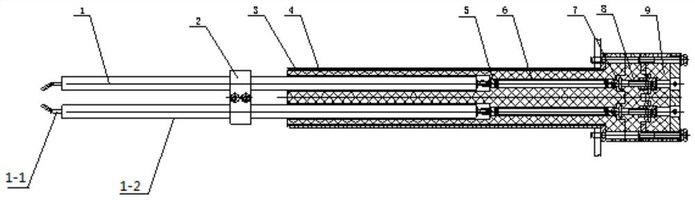
[0021] Specific implementation mode two: combination figure 1 Describe this embodiment, each telescopic assembly described in this embodiment includes a spring connector 5, a spring 6 and a connecting sleeve 7, one end of the spring 6 is connected to a corresponding electrode assembly 1 through the spring connector 5; the other end of the spring 6 One end is connected to a corresponding intermediate contact 8 through a connection kit 7 .
[0022] With such arrangement, the telescopic assembly can enable the electrode to have a telescopic function as the burner damper switch moves, which is convenient for ignition.
[0023] Other components and connections are the same as those in the first embodiment.
specific Embodiment approach 3
[0024] Specific implementation mode three: combination figure 1 Describe this embodiment, each electrode assembly 1 described in this embodiment includes an electrode 1-1 and an insulating ceramic sheath 1-2, the insulating ceramic sheath 1-2 is set on the electrode 1-1, and the ignition of the electrode 1-1 The end extends from the end of the insulating ceramic sheath 1-2.
[0025] In this way, an insulating ceramic sheath 1-2 is installed on each electrode to strengthen the insulation and enhance the oxidation resistance.
[0026] Other components are the same as those in the second embodiment in terms of connections.
specific Embodiment approach 4
[0027] Specific implementation mode four: combination figure 1 To illustrate this embodiment, an ignition device for increasing the service life of an oil-fired boiler described in this embodiment further includes a fixed platen 2, which is set in the middle of two insulating ceramic sheaths 1-2.
[0028] The pressure plate 2 is composed of the upper and lower halves of the stainless steel pressure plate. The upper pressure plate and the lower pressure plate are set opposite to each other, and are used to fix the insulating ceramic sheath outside the two electrode assemblies, and at the same time play a position-limiting role, and are also used to communicate with the burner damper. Snap connection on bezel.
[0029] Other compositions and connections are the same as those in the first, second or third embodiment.
PUM
 Abstract
Description
Claims
Application Information