Eureka AIR delivers breakthrough ideas for toughest innovation challenges, trusted by R&D personnel around the world.

Electric appliance cabinet for automatic control

A technology for automatic control and electrical appliances, which is applied in the direction of electrical equipment casings/cabinets/drawers, electrical components, electrical equipment structural parts, etc., can solve the problems of inconvenient construction and use, improve heat dissipation, avoid fire, Avoid the effect of damage

Pending Publication Date: 2020-09-18
江苏通宇建筑钢结构工程有限公司
View PDF0 Cites 3 Cited by
  • Summary
  • Abstract
  • Description
  • Claims
  • Application Information

AI Technical Summary

Problems solved by technology

[0005] The purpose of the present invention is to provide an electrical cabinet for automatic control, which solves the problem of inconvenient construction and inconvenient use caused by carrying paging equipment such as a pager separately in the prior art

Method used


Image

  • Electric appliance cabinet for automatic control
  • Electric appliance cabinet for automatic control
  • Electric appliance cabinet for automatic control

Examples


Embodiment Construction

[0030] The following will clearly and completely describe the technical solutions in the embodiments of the present invention with reference to the drawings in the embodiments of the present invention.

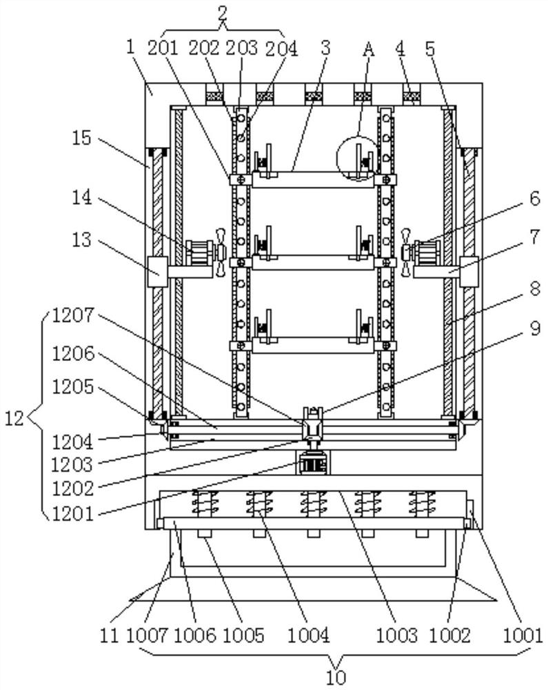
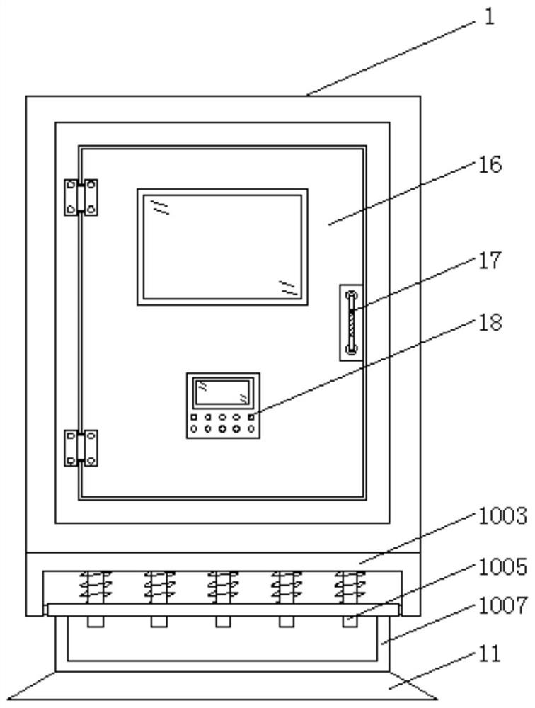
[0031] The invention provides a technical solution: an electrical cabinet for automatic control, including a cabinet body 1, a buffer mechanism 10 is installed at the bottom of the cabinet body 1, and cooling holes 4 are opened at equal intervals on the side wall of the top of the cabinet body 1, and the heat dissipation The center of the inner cavity of the hole 4 is provided with a filter screen, which is convenient to discharge the heat generated in the inner cavity of the electrical cabinet in time, and avoids the burning of the internal electrical components (see the attached drawing of the manual) figure 1 );

[0032]Buffer mechanism 10 comprises sliding cavity 1001, sliding block 1002, overcoat 1003, damping spring 1004, vertical bar 1005, movable plate 1006 and inner c...


PUM


Abstract

The invention discloses an electric appliance cabinet for automatic control. The cabinet comprises a cabinet body; a buffer mechanism is mounted at the bottom of the cabinet body; a base is mounted atone end, away from the cabinet body, of the buffer mechanism; a door body is installed on the front face of the cabinet body through a hinge shaft; a control panel is mounted at the lower end of thefront surface of the door body; a transmission mechanism is mounted at the bottom of an inner cavity of the cabinet body; a temperature sensor is mounted in the center of the top of the transmission mechanism. According to the invention, the temperature value of the inner cavity of the cabinet body is sensed through the temperature sensor; when the temperature exceeds a set value; the control panel controls a servo motor and a driving motor to work; a screw rod is driven to rotate through the transmission mechanism; when the screw rod rotates, the driving block can drive the connecting plate to move up and down, so that fan blades can move up and down conveniently; and at the moment, the driving motor drives the fan blades to rotate through a rotating shaft, electric appliance elements inthe inner cavity of the cabinet body can be cooled, the cooling effect of the electric appliance cabinet is improved, and fire disasters caused by over-high temperature are avoided.

Description

technical field [0001] The invention relates to the technical field of electrical equipment, in particular to an electrical cabinet for automatic control. Background technique [0002] Electrical cabinet equipment is a general term for generators, transformers, power lines, circuit breakers and other equipment in the power system. Electrical cabinets are widely used in industry, agriculture, military, scientific research, transportation, commerce, medical care, services and households. , with the development of science and technology, some automatic control electrical cabinets have gradually appeared, but there are still some shortcomings in the existing electrical cabinets: [0003] The heat dissipation effect of the traditional electrical cabinet is poor. During the use process, the electrical cabinet will not be able to dissipate the heat generated by the internal components, which will cause the electrical cabinet to be prone to fire and reduce the safety of the electric...

Claims


Application Information

Patent Timeline
Patent Type & Authority Applications(China)
IPC IPC(8): H05K7/20H05K5/02
CPCH05K5/0217H05K7/20554
Inventor 解荣荣曹小峰黄孙俊
Owner 江苏通宇建筑钢结构工程有限公司
Why Eureka
Eureka Blog
Learn More