Garbage crushing device for constructional engineering

A crushing device and construction engineering technology, which is applied in the field of construction engineering, can solve the problems of operator injury, inconvenient movement of the device, blockage of the feeding hole, etc., and achieve the effects of slowing down the feeding speed, improving the crushing effect, and convenient operation

Inactive Publication Date: 2020-09-22
山东水利职业学院
View PDF1 Cites 5 Cited by
  • Summary
  • Abstract
  • Description
  • Claims
  • Application Information

AI Technical Summary

Problems solved by technology

[0004] Although the above-mentioned scheme has realized the crushing of construction waste, there are still deficiencies: one is that in the above-mentioned scheme, the construction waste that has been crushed for the first time passes through the discharge hole during the process of falling, which will easily cause the discharge hole to be blocked, and the construction waste can be blocked in one time. The speed

Method used


Image

  • Garbage crushing device for constructional engineering
  • Garbage crushing device for constructional engineering
  • Garbage crushing device for constructional engineering

Examples


Embodiment 1

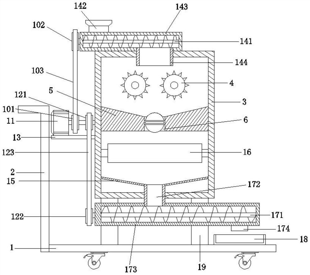
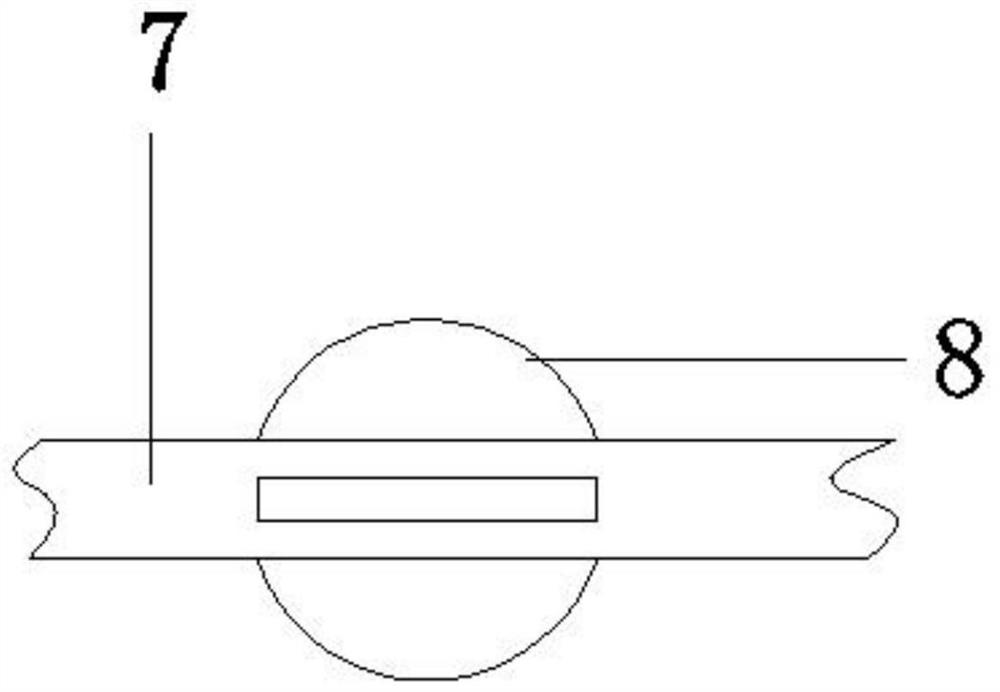
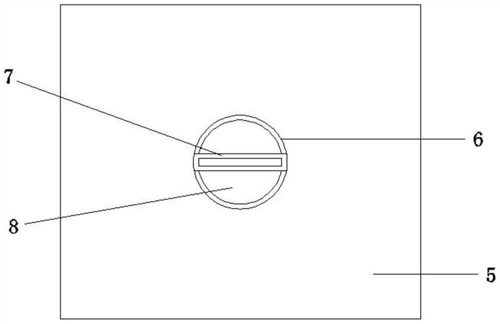
[0030] A rubbish crushing device used in construction projects comprises a base 1 with rollers, and a push handle 2 is fixed on the left end of the base 1 . The upper end of base 1 is all fixed with supporting rod 19 around, and the upper end of supporting rod 19 is fixed with casing 3, and the inside of casing 3 is fixed with pulverizer 4, and pulverizer 4 is prior art. The middle part of casing 3 is fixed with blanking seat 5, and the upper end of blanking seat 5 is arranged as funnel shape, and the middle part of blanking seat 5 is provided with blanking port 6. The internal rotation of the blanking seat 5 is limited by a rotating shaft 7, and the outside of the rotating shaft 7 is evenly provided with several rotating blades 8 inside the blanking port 6. The outer end of the box body 3 is fixed with a rectangular plate 13 , the upper end of the rectangular plate 13 is fixed with a transmission motor 11 , and the output shaft of the transmission motor 11 is connected with t...

Embodiment 2

[0032] The upper and lower sides of the output shaft of the transmission motor 11 are respectively provided with a first transmission mechanism 10 and a second transmission mechanism 12 , the upper end of the box body 3 is provided with a first transmission mechanism 14 , and the lower end of the box body 3 is provided with a second transmission mechanism 17 . The first conveying mechanism 14 is connected with the first transmission mechanism 10 , and the second conveying mechanism 17 is connected with the second transmission mechanism 12 . The first transmission mechanism 10 includes a first driving shaft 101 , a first driven shaft 102 and a first belt 103 . The first driving shaft 101 is sheathed on the outside of the output shaft of the transmission motor 11 , and the first driving shaft 101 is transmission-connected to the first driven shaft 102 through the first belt 103 . The second transmission mechanism 12 includes a second driving shaft 121, a second driven shaft 122 ...

Embodiment 3

[0034] A grinding mechanism 16 is provided inside the box body 3 below the feeding seat 5 , and a round bucket 15 is arranged at the bottom of the box body 3 . The grinding mechanism 16 includes a grinding motor 161 , a gear 162 , a grinding rod 163 and a grinding roller 164 . The symmetrical rotation of the grinding rod 163 is limited to the inside of the box body 3. The grinding roller 164 is set on the outside of the grinding rod 163, the outer end of the grinding rod 163 is set with a gear 162, and the outer end of the grinding rod 163 on either side is fixed with a grinding motor. 161. By providing the grinding mechanism 16, the primary crushed construction waste can be secondary crushed, which improves the crushing effect of the construction waste.

[0035] The working principle of this embodiment is: when in use, start the transmission motor 11, add construction waste to the inside of the first feeding pipe 142, the rotation of the transmission motor 11 drives the firs...


PUM


Abstract

The invention discloses a garbage crushing device for constructional engineering in the technical field of constructional engineering. The garbage crushing device comprises a base with rollers, wherein a pushing handle is fixed to the left end of the base; supporting rods are fixed to the periphery of the upper end of the base; a box body is fixed to the upper ends of the supporting rods; a crusher is fixed inside the box body; a discharging seat is fixed to the middle of the box body; the upper end of the discharging seat is arranged to be in a funnel shape; a discharging opening is formed inthe middle of the discharging seat; a rotating shaft is rotationally limited inside the discharging seat; a plurality of rotating blades are uniformly arranged at the position, positioned inside thedischarging opening, of the outer side of the rotating shaft; a rectangular plate is fixed to the outer end of the box body; a transmission motor is fixed to the upper end of the rectangular plate; anoutput shaft of the transmission motor is connected with the rotating shaft; and a first transmission mechanism and a second transmission mechanism are arranged on the upper side and the lower side of the output shaft of the transmission motor correspondingly. According to the garbage crushing device, the transmission motor rotates to drive the rotating blades to rotate, so that a discharging hole is prevented from being blocked, the discharging speed is reduced, the operation is convenient and fast, and dust can be prevented from escaping out of the box body in the crushing process.

Description

technical field [0001] The invention relates to the technical field of construction engineering, in particular to a garbage crushing device used in construction engineering. Background technique [0002] China is in a period of rapid economic development, and hundreds of millions of tons of construction waste are inevitably produced every year, such as cement blocks, stones, abandoned welding slag, welding rods, and small metal objects. At present, the amount of construction waste in China has accounted for the total urban waste. One-third of the amount, if not processed and utilized in time, will definitely bring adverse effects to society, environment and resources. [0003] The patent publication No. CN210545602U discloses a construction waste crushing device for construction engineering, which belongs to the field of construction waste crushing. A construction waste crushing device for construction engineering includes a box body, and the surface of the box body is provi...

Claims


Application Information

Patent Timeline
IPC IPC(8): B02C21/02B02C4/08B02C4/02B02C23/02
CPCB02C4/02B02C4/08B02C4/286B02C21/02B02C2201/06
Inventor 王海龙张宁
Owner 山东水利职业学院
Why Eureka
Try Eureka