
Tool setting device for rotary tool rest of numerically controlled lathe and method

A technology of rotary tool post and CNC lathe, which is applied in the direction of automatic control device, feeding device, metal processing equipment, etc., can solve the problems that cannot meet the requirements of high-precision processing, cannot meet the requirements of processing accuracy, and accuracy errors, etc., and achieve simple structure, Renovation cost is low and the effect of cost reduction

Pending Publication Date: 2020-09-22
YUNCHENG PLATE MARKING
View PDF0 Cites 0 Cited by
  • Summary
  • Abstract
  • Description
  • Claims
  • Application Information

AI Technical Summary

Problems solved by technology

The efficiency of knife setting by trial cutting method is very low
[0012] 2) The automatic tool setting instrument has a high degree of automation and can realize the function of fully automatic tool setting, but it cannot meet the needs of high-precision machining
For example, the cost of Marposs automatic tool setting instrument is high, and the accuracy error of the processed product after tool setting is 0.03 mm; it cannot meet the processing accuracy requirement of 0.02 mm.

Method used


Image

  • Tool setting device for rotary tool rest of numerically controlled lathe and method
  • Tool setting device for rotary tool rest of numerically controlled lathe and method

Examples


Embodiment 1

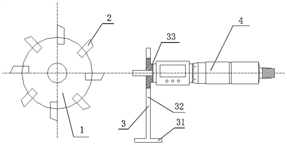
[0045] Such as figure 1 As shown, the present embodiment provides a tool setting device for a rotary tool rest of a CNC lathe, which is used for tool setting of a rotary tool rest 1 on a CNC lathe. The tool setting device includes a bracket 3 and a depth micrometer, and the bracket 3 is installed on the CNC lathe. On the top, the detection end of the depth micrometer is fixed and supported by the bracket 3, and is facing the center of the rotary tool holder, and is used to measure the height of each knife 2 of the rotary tool holder;

[0046] The support 3 includes a base 31 and a support rod 32, the base 31 is fixedly connected to the numerically controlled lathe, the support rod 32 is provided with a connecting hole, the wall of the connecting hole of the support rod 32 is provided with a locking member, and the connecting hole extends into the detection end of the depth micrometer. The locking piece is used to fix the detection end of the depth micrometer;

[0047] Install...


PUM


Abstract

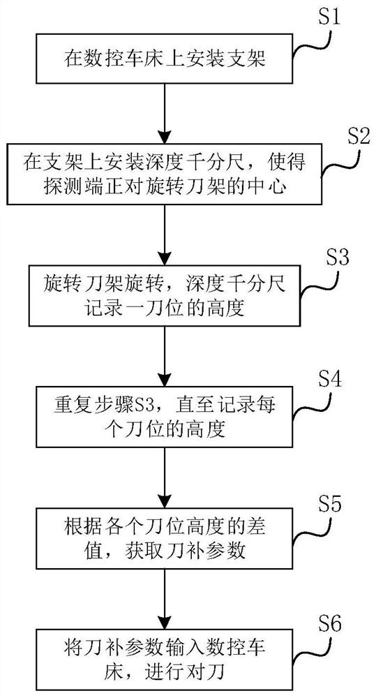
The invention relates to a tool setting device for a rotary tool rest of a numerically controlled lathe. The tool setting device for the rotary tool rest of the numerically controlled lathe is used for setting tools for the rotary tool rest on the numerically controlled lathe and comprises a support and a depth micrometer, wherein the support is installed on the numerically controlled lathe, a detection end of the depth micrometer is fixed and supported by the support and directly faces the center of the rotary tool rest, the depth micrometer is used for measuring the height of the each tool,the support comprises a base and a supporting rod, the base is fixedly connected with the numerically controlled lathe, a connecting hole is formed in the supporting rod, a locking piece is arranged on the wall of the connecting hole of the supporting rod, the connecting hole allows the detection end of the depth micrometer to stretch in, the locking piece is used for fixing the detection end of the depth micrometer, after the depth micrometer is installed and locked on the support, the height of the each tool of the rotary tool rest is measured through the depth micrometer, cutter compensation parameters are calculated according to difference values, and the cutter compensation parameters are input into the numerically controlled lathe for carrying out tool setting on the rotary tool rest. Compared with the prior art, the tool setting device has the advantages of high tool setting precision, stability, reliability, convenience in manufacturing, low cost and the like.

Description

technical field [0001] The invention relates to the field of rotary tool rests of numerical control lathes, in particular to a tool setting device and method for rotary tool rests of numerical control lathes. Background technique [0002] There are mainly the following two methods for tool setting of multiple tools on the rotary tool holder of the CNC lathe. [0003] 1. Trial cutting method for knife setting [0004] Trial cutting method is the most widely used tool setting method in practice. The process of knife setting by trial cutting method is as follows: [0005] After the workpiece and tool are clamped, the main shaft is driven to rotate, and the tool holder is moved to the workpiece to try to cut a section of outer circle. Then keep the X coordinate unchanged, move the tool away from the workpiece, and measure the diameter of the outer circle of this segment. Input it into the tool length in the corresponding tool parameters, and the system will automatically sub...

Claims


Application Information

Patent Timeline
IPC IPC(8): B23Q15/22
CPCB23Q15/22
Inventor 淮毅军
Owner YUNCHENG PLATE MARKING
Learn More