Magnetic levitation driving-based 3-DOF bionic eye movement device and movement method thereof

A motion device, 3-DPF technology, applied in the field of computer vision and bionic robots, can solve problems such as low transmission accuracy and positioning accuracy, inability to meet high-precision motion, and complex mechanical structure, so as to facilitate popularization and application and reduce contact The effect of high resistance and transmission efficiency

Inactive Publication Date: 2020-09-22
上海道简机电科技有限公司 +2
View PDF9 Cites 4 Cited by
  • Summary
  • Abstract
  • Description
  • Claims
  • Application Information

AI Technical Summary

Problems solved by technology

[0003] Most of the existing bionic eye devices are driven by mechanical transmission. Although the control is relatively simple, the mechanical structure is complex, the transmission accuracy and positioning accuracy are not high, and it cannot meet the needs of certain high-precision movements. make a lot of noise
However, for some flexible-driven bionic eye mechanisms, there is often a problem of insufficient rigidity.

Method used


Image

  • Magnetic levitation driving-based 3-DOF bionic eye movement device and movement method thereof
  • Magnetic levitation driving-based 3-DOF bionic eye movement device and movement method thereof
  • Magnetic levitation driving-based 3-DOF bionic eye movement device and movement method thereof

Examples


Embodiment 1

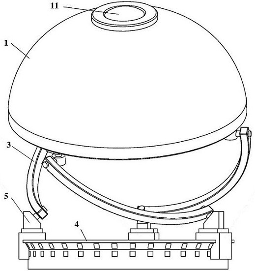
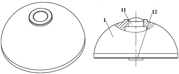
[0029] A 3-DOF bionic eye movement device based on magnetic levitation drive, such as figure 1 and figure 2 As shown, it includes the bionic eyeball 1 and the three-degree-of-freedom spherical parallel mechanism that drives the bionic eyeball 1 to rotate. The camera 11 is embedded inside the bionic eyeball 1; Above: The three-degree-of-freedom spherical parallel mechanism drives the bionic eyeball 1 to rotate through magnetic levitation.

[0030] The three-degree-of-freedom spherical parallel mechanism includes a motion platform 2 fixed at the bottom of the bionic eyeball 1, a magnetic levitation guide rail 4 located below the motion platform 2, and three arc-shaped drive rods with the same structure and size connecting the magnetic levitation guide rail 4 and the motion platform 2 3. The bottom ends of the three arc-shaped driving rods 3 are all connected to the magnetic levitation guide rail 4 through the corresponding sliders 5 one by one. The magnetic levitation guide r...

Embodiment 2

[0038] Utilize the 3-DOF bionic eye movement device based on magnetic levitation drive in embodiment 1 to adjust the method for bionic eye movement, such as Figure 7-9 As shown, the details are as follows:

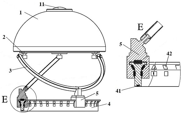
[0039] At the initial position of the bionic eyeball 1, the central axis of the bionic eyeball 1 is perpendicular to the horizontal plane; Figure 7 and Figure 8 As shown, the upper and lower ends of each arc-shaped driving rod 3 are respectively connected with the connecting pair 21 fixed on the motion platform 2 and the rotating pair 52 fixed on the slider 5, and the connection of the same arc-shaped driving rod 3 is connected. Vice 21, rotation vice 52 are arranged alternately.

[0040] When the field of view of the bionic eyeball 1 needs to be adjusted, the magnetic levitation control system 41 is used to control the direction and magnitude of the magnetic force of the guide rail magnetic sheet, and to control the attraction, repulsion and force strength between th...


PUM


Abstract

The invention belongs to the field of computer vision and bionic robots, and relates to a high-precision bionic eye device, in particular to a magnetic levitation driving-based 3-DOF bionic eye movement device and a movement method thereof. The magnetic levitation driving-based 3-DOF bionic eye movement device comprises a bionic eyeball and a three-degree-of-freedom spherical parallel mechanism which drives the bionic eyeball to rotate; a camera device is fixed to the bionic eyeball; and the three-degree-of-freedom spherical parallel mechanism drives the bionic eyeball to rotate through magnetic levitation. The magnetic levitation driving-based 3-DOF bionic eye movement device and the movement method thereof, the mode of driving the bionic eyeball to rotate by adopting the magnetic levitation is adopted; compared with the existing mechanical connecting rod transmission mode, the mechanical structure is simpler; the transmission precision is higher; and the noise is lower.

Description

technical field [0001] The invention belongs to the field of computer vision and bionic robot, relates to a high-precision bionic eye device, in particular to a 3-DOF bionic eye movement device based on magnetic levitation drive and a movement method thereof. Background technique [0002] With the rapid development of computer vision and bionic robotics, a vision platform that can quickly and flexibly change the field of view has become particularly important. The most artistic product of nature - the human eye has received attention. Realizing a visual platform similar to the human eye will be a major breakthrough for research in the above fields. Therefore, research on bionic eye devices has become more and more popular. [0003] Most of the existing bionic eye devices are driven by mechanical transmission. Although the control is relatively simple, the mechanical structure is complicated, the transmission accuracy and positioning accuracy are not high, and it cannot mee...

Claims


Application Information

Patent Timeline
Patent Type & Authority Applications(China)
IPC IPC(8): B25J19/04B25J9/00
CPCB25J9/00B25J9/0009B25J19/04
Inventor 杨小康李恒宇陶钧傅中忠陈欣李磊王涛
Owner 上海道简机电科技有限公司
Why Eureka
Try Eureka