A casing laminating machine
A technology of laminating machine and laminating mechanism, which is applied in packaging and other directions to achieve the effect of reducing manual operations
- Summary
- Abstract
- Description
- Claims
- Application Information
AI Technical Summary
Problems solved by technology
Method used
Image
Examples
Embodiment 1
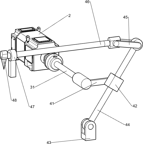
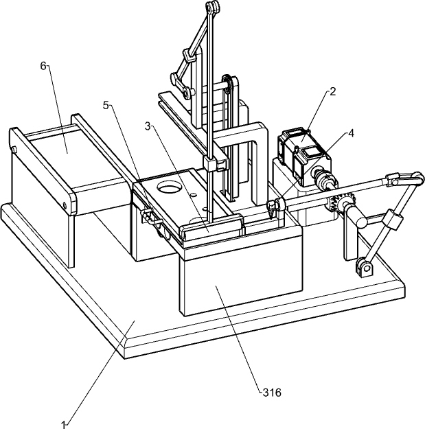
[0036] A shell coating machine, such as figure 1 Accordingly, including the mount 1, the motor 2, the film mechanism 3 and the crop mechanism 4, the motor 2 is provided on the right side of the mounting seat 1, and the mounting seat 1 is provided with a coating mechanism 3, and the coating mechanism 3 is connected to the motor 2. The front portion of the mounting seat 1 is mounted with a crop mechanism 4, and the cropping mechanism 4 is connected to the coating mechanism 3.
[0037] When the product housing is needed, the product housing is placed in the component of the coating mechanism 3, and manually pulls the protective film to the product housing and completely covers the product housing, then activates the motor 2, the output shaft of the motor 2 The components within the coating mechanism 3 are rotated clockwise, and the coating member 3 is reciprocated before and after, at the same time, the components in the film cover mechanism 3 rotate the components within the croppin...
Embodiment 2
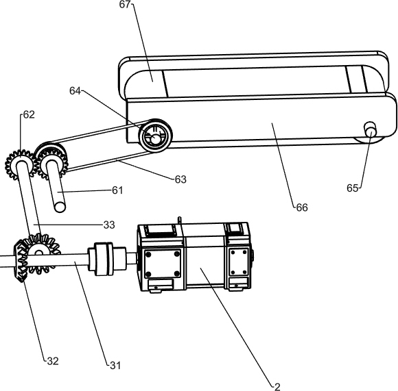
[0039] Specifically, such as Figure 1-3 As shown, the coating mechanism 3 includes an output rotating shaft 31, a cone gear assembly 32, a first rotating shaft 33, a first belt assembly 34, a second axis 35, a first rotor 36, a first swing rod 37, a first guide 38 The support rod 39, the pressure rod 310, the T type slide 311, the T-type slider 312, the slider 313, the film barrel 314, the discharge frame 315 and the table 316, and the output shaft is connected to the output shaft of the motor 2. 31. The mounting seat 1 is provided with a table 316, and the top right side of the table 316 is opened. The top wall bottom rotation of the table 316 has a first rotating shaft 33, and the first axis 33 is provided on the right side and the output rotation shaft 31. There is a cone gear assembly 32, and the top right rotation of the table 316 is connected to the second axis 35, and the first belt assembly 34 is connected between the second shaft 35 and the first rotating shaft 33, the fi...
Embodiment 3
[0044] Refer figure 1 and Figure 4-5 Further comprising discharge means 5, 5 comprises a discharge mechanism 51 and the feed plate spring 52, the left sliding table 316 is provided with the feed plate 51, the material 51 is located within the discharge block 315, block 315 discharge the right feed plate bottom feed plate spring 52 is connected between the base 51 on the right side.
[0045] Manually feed plate 51 out to the left feed plate 51, spring 52 is stretched manually to be coated product housing is placed on the feed plate 51, loosen the feed plate 51, under the action of spring 52, feed plate 51 after reset automatically to the right, when the feed plate 51 on the housing cover good film products, artificial again out to the left feed plate 51, the housing cover taken good shell membrane products, coating products to be placed on the housing shell can be, so good coating film can easily be taken out of the product housing.
[0046] Further comprising an automatic transpor...
PUM
 Abstract
Description
Claims
Application Information
 - R&D
- Intellectual Property
- Life Sciences
- Materials
- Tech Scout
- Unparalleled Data Quality
- Higher Quality Content
- 60% Fewer Hallucinations
Browse by: Latest US Patents, China's latest patents, Technical Efficacy Thesaurus, Application Domain, Technology Topic, Popular Technical Reports.
© 2025 PatSnap. All rights reserved.Legal|Privacy policy|Modern Slavery Act Transparency Statement|Sitemap|About US| Contact US: help@patsnap.com


