A straw winding device

A winding device and straw weaving technology, which is applied in the directions of transportation and packaging, thin material handling, transportation of filamentous materials, etc., can solve problems such as affecting work efficiency, easy deviation of straw ropes, uneven winding, etc., to improve work efficiency. The effect of efficiency

Active Publication Date: 2021-11-23
邓志香
View PDF6 Cites 0 Cited by
  • Summary
  • Abstract
  • Description
  • Claims
  • Application Information

AI Technical Summary

Problems solved by technology

[0005] In order to overcome the disadvantages of constantly moving hands back and forth for winding, human hands are prone to soreness and affect subsequent work efficiency, and in the process of winding, the grass rope is easy to deviate from the position and cause the winding to be uneven. The technical problems to be solved are: Provide a straw braided winding device that is more convenient for people to wind up the straw rope, has high work efficiency, and the rolled straw rope is neat

Method used


Image

  • A straw winding device
  • A straw winding device
  • A straw winding device

Examples


Embodiment 1

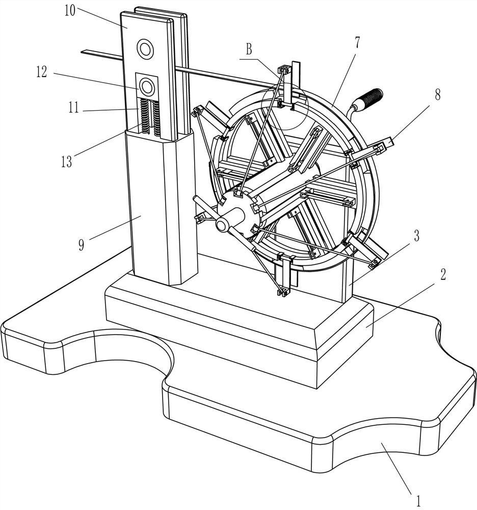
[0025] see Figure 1-Figure 4 , a straw weaving rolling device, including a base 1, a support block 2, a vertical plate 3, a bearing seat 4, a rotating shaft 5, a rocker 6 and a winding mechanism 7, a support block 2 is fixed in the middle of the top of the base 1, and the support block 2. A riser 3 is fixedly connected to the rear part on the right side of the top, and a bearing seat 4 is embedded in the middle of the upper part of the riser 3. The inner part of the bearing seat 4 is connected with a rotating shaft 5 with interference, and the rear end of the rotating shaft 5 is fixedly connected with a rocker 6. The rotating shaft 5. The front end is provided with a winding mechanism 7.

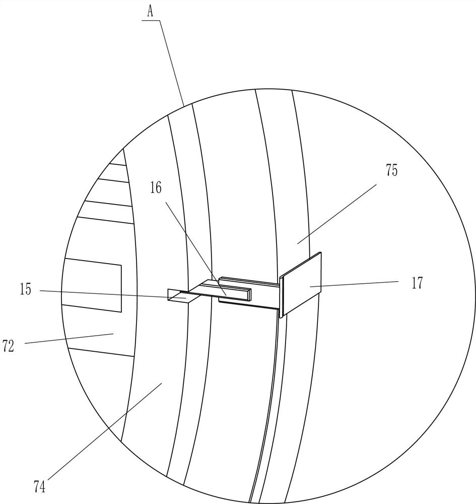
[0026] The winding mechanism 7 includes a rotating drum 71, a guide rail 72, a vertical slide block 73, an annular ring 74, an arc block 741, a top block 75, a slide block 77, a disc 78, a handle 79 and a connecting rod 710, and the front end of the rotating shaft 5 A rotating cylinder 71 ...

Embodiment 2

[0030] see figure 1 , image 3 and Figure 7 Compared with Embodiment 1, the main difference of this embodiment is that in this embodiment, a limit mechanism 8 is also included, and the limit mechanism 8 includes a fixed limit plate 81, a rotating rod 82, a square block 83, a fixed plate 84, a second An elastic sheet 85, movable limit plate 86 and connecting rod 87, the bottom of the left and right sides of the arc block 741 are all affixed with a fixed plate 84, and the front and rear sides of the outer side of the fixed plate 84 are all affixed with the first elastic sheet 85. The ends of adjacent arc-shaped blocks 741 are rotatably connected with rotating rods 82, and the two parts of the rotating rods 82 are fixedly connected with square blocks 83, and the square blocks 83 are in contact with the first elastic sheets 85 on the front and rear sides. Cooperate, rotating bar 82 outer side middle parts are fixedly connected with the movable limiting plate 86 that can limit t...

Embodiment 3

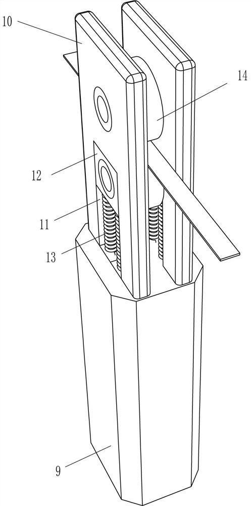
[0033] see figure 1 , figure 2 , Figure 5 and Figure 6 The main difference between this embodiment and embodiment 1 and embodiment 2 is that this embodiment also includes a support seat 9, a support plate 10, a guide block 12, an elastic member 13 and a guide roller 14, and the top left of the support block 2 The front part of the side is fixedly connected with a support seat 9, and the front and rear sides of the top of the support seat 9 are fixedly connected with a support plate 10. There is a guide groove 11 in the middle of the lower part of the support plate 10, and a guide block 12 is slidingly provided in the guide groove 11. Elastic parts 13 are connected between the left and right sides of the bottom of the guide block 12 and the top of the support seat 9, and guide rollers 14 are rotatably connected between the middle parts of the guide blocks 12 on the front and rear sides, and the upper parts of the support plates 10 on the front and rear sides are also rotat...


PUM


Abstract

The invention relates to a winding device, in particular to a straw winding device. The technical problem is how to design a straw braided winding device that can be more convenient for people to wind up the straw rope, has high work efficiency, and the straw rope that is rolled up is also neat. A straw weaving and rolling device, including a base, a support block is fixedly connected to the middle part of one side of the base, a vertical plate is fixedly connected to the edge of one side of the support block, and the bearing seat is embedded and installed on the side far away from the support block. One part of the vertical plate, the shaft is rotatably connected in the bearing seat. In the present invention, by winding the straw rope around all the top blocks, and then pulling the rocker to rotate forward, the top block can be rotated forward to wind up the straw rope. After the straw rope is rolled up, pull the handle to move forward to make the top block Move inward to loosen the straw rope, and then take off the rolled straw rope, so that people don't need to pull the straw rope to wrap it around the tool for winding, which is more convenient and improves work efficiency.

Description

technical field [0001] The invention relates to a winding device, in particular to a straw winding device. Background technique [0002] Straw weaving is a handicraft that is widely popular among the people. It uses the grass produced in various places to weave various daily necessities, such as baskets, fruit boxes, cup covers, pot mats, hats, slippers and pillow mats. Some use grass dyed with various colors in advance to weave various patterns, while others print decorative patterns after weaving. It is economical, practical, and beautiful. When weaving straw, straw rope is generally used to weave different kinds of handicrafts. However, straw rope is very messy and needs to be rolled up for subsequent use. [0003] At present, most of them are rewound by manually pulling the straw rope, which requires people to wrap the straw rope around the designated tool for winding, and then remove the rewound straw rope. Continuously moving back and forth for winding, after a long...

Claims


Application Information

Patent Timeline
Patent Type & Authority Patents(China)
IPC IPC(8): B65H54/74B65H54/54B65H57/06B65H57/14
CPCB65H54/54B65H54/74B65H57/06B65H57/14B65H2404/14B65H2701/35
Inventor 葛伟邓志香
Owner 邓志香
Why Eureka
Try Eureka