
Full-automatic supply line for canned chlorine

A supply line, fully automatic technology, applied in the direction of lifting device, hoisting device, transportation and packaging, etc., can solve the problems of chlorine gas leakage, leakage, affecting environmental safety, etc., to achieve the effect of zero emissions to the atmosphere

Pending Publication Date: 2020-09-22
德州凯密迪化工有限公司
View PDF0 Cites 0 Cited by
  • Summary
  • Abstract
  • Description
  • Claims
  • Application Information

AI Technical Summary

Problems solved by technology

[0003] 1. In the existing automatic feeding system for canned chlorine gas, external personnel need to use hoisting equipment to hoist, and then use lifting equipment to lift the chlorine gas tank into the working station. This kind of operation has a large workload, and There are certain safety hazards in the chlorine gas supply area
[0004] 2. The existing chlorine gas supply tank does not have an automatic weighing device. After the chlorine gas tank is fixed, it can only be inspected regularly by personnel. Because the chlorine gas supply area is dangerous, there are potential safety hazards when personnel often enter
[0005] 3. There will be a small amount of chlorine leakage when the chlorine tank is replaced. At present, there is no special recovery device, which can only make it leak into the atmosphere and affect environmental safety.
[0006] 4. During the use of chlorine gas, if there is a safety leak in the chlorine gas tank or joints and cannot be remedied in a short time, the chlorine gas tank can only be placed in the pool. The current treatment method is to dig a pool deep on the ground in the chlorine gas supply area. When there is a safety hazard, the operator lifts the chlorine gas tank into the pool to prevent the chlorine gas from spreading, but this operation method is cumbersome, slow in efficiency and poses a safety hazard to the life of the operator

Method used


Image

  • Full-automatic supply line for canned chlorine
  • Full-automatic supply line for canned chlorine
  • Full-automatic supply line for canned chlorine

Examples


Embodiment Construction

[0028] In order to make the object, technical solution and advantages of the present invention clearer, the present invention will be further described in detail below in conjunction with the accompanying drawings. It should be understood that the specific embodiments described here are only used to explain the present invention, and are not intended to limit the present invention.

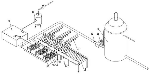
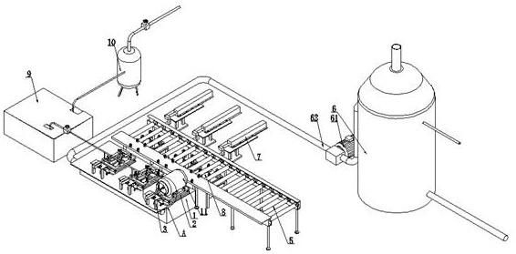
[0029] As shown in the attached figure, a fully automatic supply line for canned chlorine gas, such as figure 1 , 2 As shown, it includes a supply platform 1 and a chlorine tank delivery line 5;

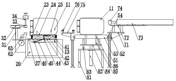
[0030]The chlorine gas tank conveying line 5 is arranged on the front side of the supply table 1, and its setting purpose is to realize the conveyance of the chlorine gas tank filled with chlorine from the outside to the inside or the conveyance of the empty tank from the inside to the outside, which includes a conveying frame body 51, The top of the conveyor frame body 51 is provided with a plurality ...


PUM


Abstract

The invention discloses a full-automatic supply line for canned chlorine. The full-automatic supply line for canned chlorine is provided with a chlorine tank conveying line arranged corresponding to asupply table, a horizontal push cylinder is arranged on the chlorine tank conveying line, an external lifting structure is arranged in the chlorine tank conveying line, and the external lifting structure is matched with internal lifting structures arranged in weighing modules to realize vertical lifting so as to realize the longitudinal movement of a chlorine tank; a water pool is arranged in thesupply table, the multiple weighing modules are hinged above the water pool, and the weighing modules can be connected with an external alarm device to realize alarm prompt under the condition of insufficient weight; furthermore, the weighing modules are fixed in a horizontal hinged mode, one end of each weighing module is provided with a movable block capable of realizing plug-in support to support and erect the chlorine tank, and when a critical situation occurs, the movable blocks are driven to be separated from the support in a manual or automatic mode so that the chlorine tank can automatically fall into the water pool.

Description

technical field [0001] The invention relates to the technical field of canned chlorine gas supply equipment, in particular to an automatic canned chlorine gas supply line. Background technique [0002] As we all know, in the field of calcium chloride production technology, chlorine is usually supplied in a gaseous state using a canned structure; when the existing chlorine gas is supplied, it is first fixed on the bracket, and the chlorine tank and the installation joint are fixed through the manual installation structure To achieve gas supply after opening the valve in one piece, however, there are many disadvantages in this supply method, which are reflected in the following points: [0003] 1. In the existing automatic feeding system for canned chlorine gas, external personnel need to use hoisting equipment to hoist, and then use lifting equipment to lift the chlorine gas tank into the working station. This kind of operation has a large workload, and There are certain saf...

Claims


Application Information

Patent Timeline
IPC IPC(8): B66F19/00B66F7/16B65G13/06B65G13/00B65G47/74
CPCB65G13/00B65G13/06B65G47/74B66F7/16B66F19/00
Inventor 张世军
Owner 德州凯密迪化工有限公司
Learn More