
Electromagnetic array type driving device for knitting needle flat knitting machine and control method thereof

A technology of a driving device and a control method, applied in the directions of knitting, weft knitting, textile and papermaking, etc., can solve the problems of low knitting efficiency and poor knitting effect, and achieve the effect of improving knitting efficiency and knitting effect.

Active Publication Date: 2020-09-22
WUHAN TEXTILE UNIV
View PDF8 Cites 4 Cited by
  • Summary
  • Abstract
  • Description
  • Claims
  • Application Information

AI Technical Summary

Problems solved by technology

[0004] The purpose of the present invention is to overcome the defects and problems of low knitting efficiency and poor knitting effect in the prior art, and provide an electromagnetic array driving device and its control method for knitting needle flat knitting machines with high knitting efficiency and good knitting effect

Method used


Image

  • Electromagnetic array type driving device for knitting needle flat knitting machine and control method thereof
  • Electromagnetic array type driving device for knitting needle flat knitting machine and control method thereof
  • Electromagnetic array type driving device for knitting needle flat knitting machine and control method thereof

Examples


Embodiment

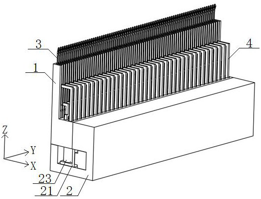
[0048] See figure 1 , An electromagnetic array drive device for a knitting needle flat knitting machine, comprising an upper frame 1, a lower frame 2 and a connecting rod 4, wherein the upper frame 1 is connected with the lower frame 2;

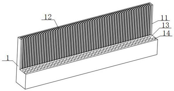
[0049] See Figure 2 to Figure 5 , The upper frame 1 has an L-shaped structure, and a plurality of needle grooves 12 are uniformly opened on the first inner side surface 11 of the upper frame 1 along the Y-axis direction, and two inner side walls of the needle groove 12 are both installed No. permanent magnet 6, the needle groove 12 is inserted with the knitting needle 3, and the second inner side surface 13 of the upper frame 1 is sequentially provided with a first row of blind holes 141 and a second row of blind holes 142 along the X-axis direction;

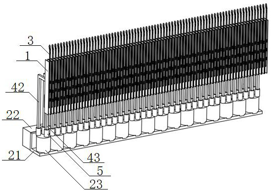
[0050] See Figure 8 to Figure 10 The connecting rod 4 includes a first connecting rod 42 and a second connecting rod 43, the first connecting rod 42 includes a first rod 421 and a second rod 422, ...


PUM


Abstract

The invention discloses an electromagnetic array type driving device for a knitting needle flat knitting machine. The electromagnetic array type driving device for the knitting needle flat knitting machine comprises an upper machine frame and a lower machine frame; a plurality of needle slots are formed in a first inner side surface of the upper machine frame; No. 2 permanent magnets are mounted on both two inner side walls of each needle slot; a knitting needle is inserted into each needle slot; one or more rows of blind holes are formed in a second inner side surface of the upper machine frame; connecting rods are inserted into the blind holes; one end, positioned at the bottom of the blind hole, of each connecting rod is connected with a No. 1 permanent magnet; the other end of each connecting rod is connected to the corresponding knitting needle after extending into the corresponding needle slot, and No. 3 permanent magnets with the same polarity as the No. 2 permanent magnets aremounted on both sides of the end; a mounting seat and a motor module which are connected are arranged in the lower machine frame; the mounting seat can move reciprocally in a Y-axis direction; a plurality of mounting holes are formed in the mounting seat; electromagnets are mounted in the mounting holes; and the electromagnets are positioned below the plurality of the No. 1 permanent magnets. Through the design, the knitting efficiency and the knitting effect are improved, and the service lives of the knitting needles are prolonged.

Description

Technical field [0001] The invention relates to the technical field of textiles, in particular to an electromagnetic array type driving device for a flat knitting needle knitting machine and a control method thereof, and is mainly suitable for improving the knitting efficiency and the knitting effect. Background technique [0002] In the field of textile machinery, the jacquard circular knitting machine performs jacquard on the fabric to weave various patterns and patterns. The electronic needle selection devices of the existing knitting needle computer jacquard circular knitting machine are mainly electromagnetic and piezoelectric. They all use mechanical parts such as triangle cams, jacquard sheets, and needle jacks to realize needle selection. The cam contact realizes the up and down knitting movement. Therefore, the triangular cam in the knitting mechanism causes impact friction and lateral force on the knitting needles. With the continuous increase of the speed of the needl...

Claims


Application Information

Patent Timeline
Patent Type & Authority Applications(China)
IPC IPC(8): D04B15/22D04B15/99D04B15/96
CPCD04B15/22D04B15/96D04B15/99
Inventor 张成俊李冬冬戴健雄刘雅昆左小艳张弛朱里
Owner WUHAN TEXTILE UNIV
Learn More