Cutter suction dredging device easy to rotate

A telescopic device and turntable technology, which is applied to mechanically driven excavators/dredgers, motor vehicles, transportation and packaging, etc., can solve the problems of high cost and low efficiency of hull rotation, achieve small fluctuations, reduce labor costs, Highly stable effect

Active Publication Date: 2020-09-22
海南河道综合整治工程有限公司
View PDF5 Cites 2 Cited by
  • Summary
  • Abstract
  • Description
  • Claims
  • Application Information

AI Technical Summary

Problems solved by technology

[0003] The purpose of the present invention is to address the deficiencies in the above-mentioned technologies, and propose a hinged suction dredging device that is easy to rotate, aiming at solving the problem that the above-mentioned hull needs to be rotated by using anchor cables to pull the hull, and the rotation efficiency of the hull is low and the cost is high. question

Method used


Image

  • Cutter suction dredging device easy to rotate
  • Cutter suction dredging device easy to rotate
  • Cutter suction dredging device easy to rotate

Examples


Embodiment 1

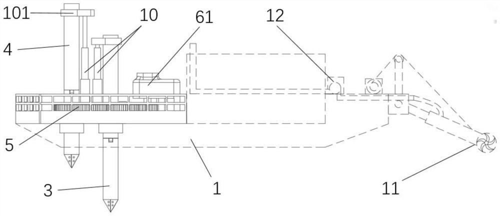
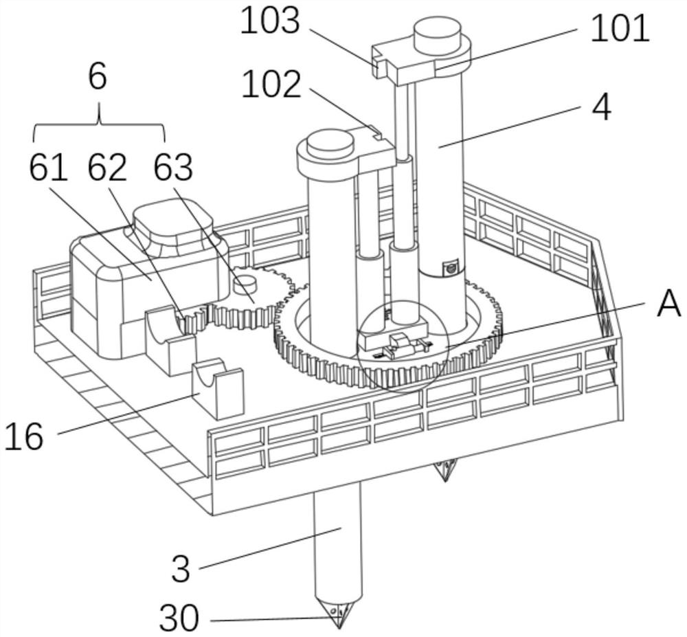
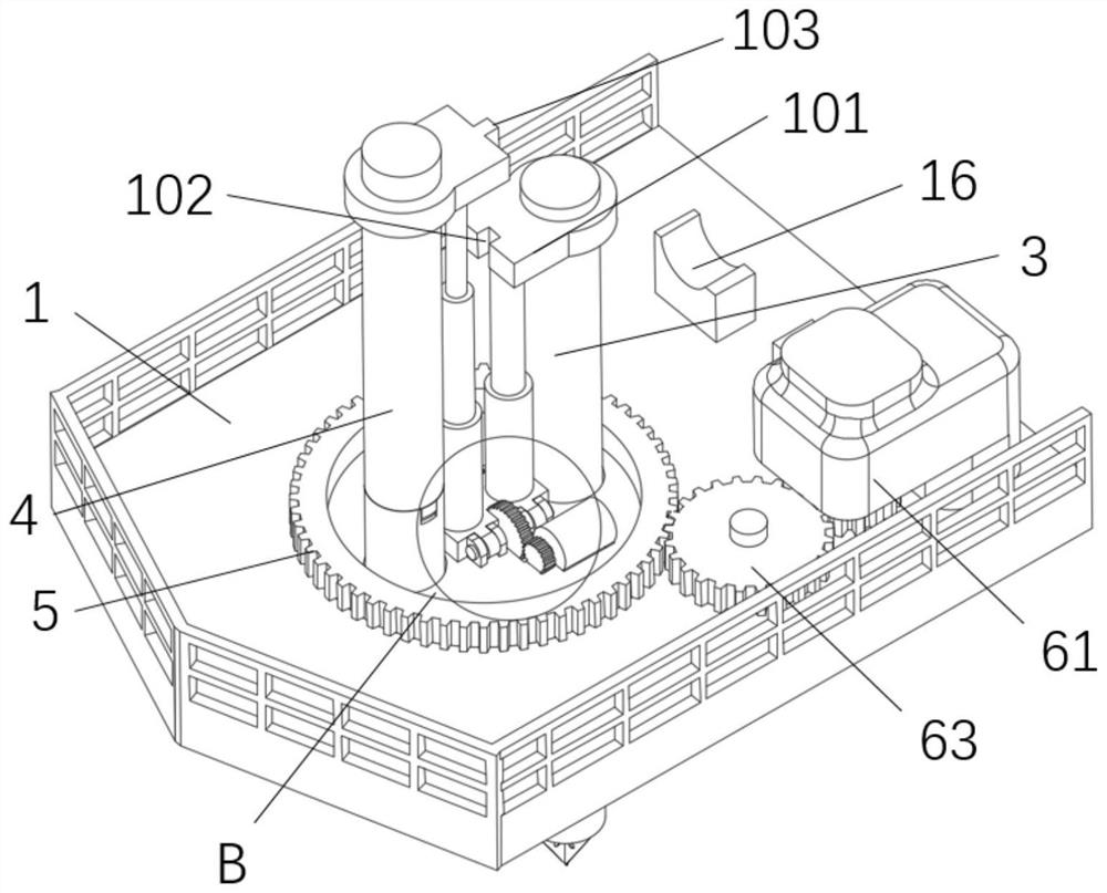
[0038] Such as Figure 1 to Figure 12 As shown, the present invention provides a kind of hinged suction dredging device that is convenient to rotate, comprises hull 1, and one end of hull 1 is provided with hinged suction head 11, and hull 1 is also provided with the mud pump 12 that communicates with hinged suction head 11 , to suck the sludge at the bottom of the river into the pipeline connected to the mud pump 12 by hinge suction head 11; it also includes a turntable 2, which is rotatably arranged at one end of the hull 1; the turntable 2 can be raised and lowered A first positioning pile 3 and a second positioning pile 4 are provided to lower and insert the first positioning pile 3 and the second positioning pile 4 into the bottom of the river for positioning; the turntable 2 is provided with a ring gear 5, and the hull 1 is provided with a driving The power unit 6 that the ring gear 5 rotates drives the ring gear 5 to rotate through the power unit 6, thereby driving the ...

Embodiment 2

[0045] Such as Figure 5 and Figure 10 As shown, in combination with the technical solution of embodiment 1, in this embodiment, the turntable 2 is provided with an annular semicircular groove 23, and the hull 1 is provided with an annular stopper groove 13 corresponding to the annular semicircular groove 23, and the annular semicircular groove 23 and the annular limiter The bit groove 13 is rotatably connected by the ball 14, so that the turntable 2 can be rotatably arranged on the hull 1, and the position of the first positioning pile 3 and the second positioning pile 4 can be adjusted by the rotation of the turntable 2; when the first positioning pile 3 and the second positioning pile 4 are inserted into the river bottom at the same time, the turntable 2 is fixed, and the power device 6 moves on the ring gear 5 to drive the hull 1 to rotate; when the first positioning pile 3 or the second positioning pile 4 is inserted separately At the bottom of the river, the first posi...

Embodiment 3

[0050] Such as figure 2 and image 3 As shown, in combination with the technical solutions of Embodiment 1 and Embodiment 2, in this embodiment, a groove 102 is provided on the socket portion 101 located on the first positioning pile 3, and a groove 102 is provided on the socket portion located on the second positioning pile 4. 101 is provided with a protrusion 103 corresponding to the groove 102, and the protrusion 103 is slidably matched with the groove 102 to lift the first positioning pile 3 and the second positioning pile 4 to the top through the telescopic device 10, so that the protrusion 103 103 enters into the groove 102 to lock the sleeve part 101 on the first positioning pile 3 and the second positioning pile 4, thereby avoiding the sleeve during the folding process of the first positioning pile 3 and the second positioning pile 4 The problem of rotation of the connecting part 101 arises, which effectively improves the accuracy and stability of the folding.

[00...


PUM


Abstract

The invention discloses a cutter suction dredging device easy to rotate. By arranging a turntable that can rotate relative to a hull and positioning by double positioning piles, the hull can rotate around the positioning piles without using anchor cables to pull the hull to rotate, and the rotation efficiency of the hull is greatly improved; by eliminating the complicated operations of pulling thehull to rotate by the anchor cables, the rotation flexibility of the hull is effectively improved; meanwhile, the arrangement of an anchor cable driving device on a river bank is avoided, the dredging cost is greatly reduced, and the labor cost is reduced; a single positioning pile on the turntable goes deep into a river bottom for positioning, and the turntable is rotated to drive the hull to step, so that the stepping and advancing efficiency of the hull can be effectively improved; in addition, the positioning piles are folded by folding assemblies so as to improve the passing rate of thehull; and finally, for a wider river channel, a cutter suction head has small fluctuation and high stability under the action of no anchor cable connection on both sides.

Description

technical field [0001] The invention relates to the technical field of hinged suction dredging, in particular to a hinged suction type dredging device which is easy to rotate. Background technique [0002] The cutter suction ship is a kind of engineering ship used for dredging and filling projects, which is suitable for excavating sandy soil, silt and other soils with relatively loose river bottoms. It is mostly used for construction in inland rivers, lake areas and coastal port areas. It is one of the existing dredgers. The main one. There are two positioning piles at the stern of this dredger. When dredging, one of them is inserted into the river bottom as a positioning pile, and the dredger is pulled by an anchor cable. With the positioning pile as the center, it swings left and right to dredge. , like walking on two legs, use another steel column to replace piles alternately, and the hinged suction head is fan-shaped during the dredging process; since the hinged suction...

Claims


Application Information

Patent Timeline
Patent Type & Authority Applications(China)
IPC IPC(8): E02F5/28E02F3/88E02F3/90E02F3/92B63B21/50B63B35/00
CPCE02F5/28E02F3/885E02F3/907E02F3/9212B63B21/50B63B35/00
Inventor 杨建青任永杨明虎唐于伟谢碧鸿
Owner 海南河道综合整治工程有限公司
Why Eureka
Try Eureka